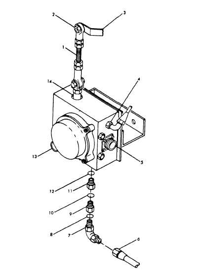
3-176. Removal, of Sump and Filter.
Figure 3-32. Hydraulic Actuator Servicing (MEP105A)
1. Throttle linkage
2. Nut self-locking
3. Lever arm
4. Return Adapter
5. Connector J25
6. Hose
7. Elbow assembly bulkhead
8. Packing
9. Reducer expander
10. Packing
11. Filter plug
12. Packing
13. Connector J24
14. Piston
d. See figure 3-33 and remove sump and filter as illustrated.
a. Remove plug (1, fig. 3-33) on sump tank (21). Drain sump
and discard oil.
3-177. Cleaning and Inspection of Sump and Filter.
b. Remove hose assembly (2) from elbow assembly (7). Remove
two loop clamps and associated hardware front of engine.
a. Cleaning.
—
c. Remove hose assembly (3) from elbow assembly (7) and from
(1) Flush sump tank (21) thoroughly with hot water or steam
elbow assembly (3A).
under pressure.
C h a n g e 1 1
3 - 8 5

