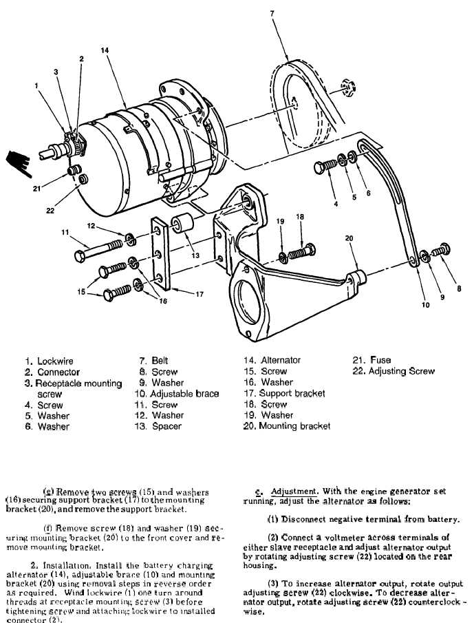
1.
Lockwire
7.
Belt
2,
Connector
8.
Screw
3. Receptacle mounting
9.
Washer
screw
10. Adjustable brace
4.
Screw
11.
Screw
5.
Washer
12.
Washer
6. Washer
13.
Spacer
14,
Alternator
21.
Fuse
15.
Screw
22. Adjusting Screw
16.
Washer
17. Support bracket
18.
Screw
19.
Washer
20. Mounting bracket
F i g u r e 3 - 3 6 . A l t e r n a t o r a n d R e l a t e d P a r t s
(Q) Remove two screws (15) and washers
(16) securing support bracket (17) to the mounting
bracket (20), and remove the support bracket.
(j) Remove screw (18) and washer (19) sec-
uring mounting bracket (20) to the front cover and re-
move mounting bracket.
2. Installation. Install the battery charging
alternator (14), adjustable brace (10) and mounting
bracket (20) using removal steps in reverse order
as required.
Wind lockwire (1) one turn around
threads at rcct-ptacle mounting screw (3) before
tightening screw and attach:ng iockwlre to Installed
comector (2).
c.
Adjustment. With the engine generator set
run;ing, adjust the alternator as follows:
(1) Discomect negative terminal from battery.
(2) Comect a voltmeter across terminals of
either slave receptacle ad adjust alternator output
by rotating adjusting screw (22) located on the rear
housing.
(3) To increase alternator output, rotate output
adjusting screw (22) clockwise. To decrease alter-
nator output, rotate adjusting screw (22) countercIock -
wise.
3 - 9 0
C h a n g e
1
2