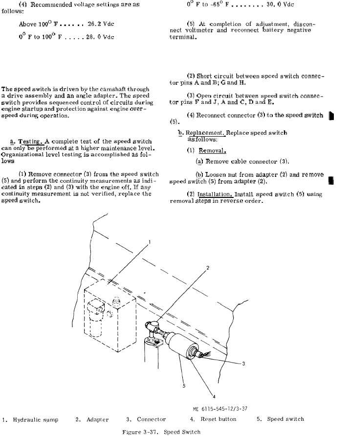
Figure 3-37.
(4)
follows:
Recommended
Above 100° F . . . .
voltage settings are as
. .
26.2 Vdc
O°Fto 1000 F..... 28. OVdc
S e c t i o n X X I X .
3 - 1 8 5 .
G e n e r a l .
The speed switch is driven by the camshaft through
a drive assembly and an angle adapter. The speed
switch provides sequenced control of circuits during
engine startup and protection against engine over-
speed during’ operation.
3 - 1 8 6 .
T e s t i n g
a n d
R e p l a c e m e n t .
a. Testing. A complete test of the speed switch
can–only be performed at a higher maintenance level.
Organizational level testing is accomplished as fol-
lows ( s e e f i g . 3 - 3 7 ) .
(1) Remove connector (3) from the speed switch
(5) and perform the continuity measurements as indi-
cated in steps (2) and (3) with the engine off. If any
continuity measurement is not verified, replace the
speed switch.
0°Fto-650F . . . . . . ..30. OVdc
(5)
At
completion
of
adjustment,
discon-
nect voltmeter and reconnect battery negative
terminal.
S P E E D
S W I T C H
(2) Short circuit between speed switch connec-
tor pins A and B; G and H.
(3) open circuit between speed switch connec-
tor pins F and J, A and C, D and E.
(4) Reconnect connector (3) to the speed switch
(5).
Q. Replacement.
Replace speed switch
( 5 ,
f i g .
3 - 3 7 ) as follows:
(1)
Removal.
(~) Remove cable connector (3).
(Q) Loosen nut from adapter (2) and remove
speed switch (5) from adapter (2).
(2) Installation. Install speed switch (5) using
removal steps in reverse order.
C h a n g e
3
3 - 9 1