TM 5-6115-465-34
TO 35C2-3-446-2
NAVFAC P-8-625-34
TM 06858B/06859D-34
d.
Assembly.
(6) Disconnect water inlet housing (15) by re-
moving screw (13) and lockwasher (14). Discard gas-
ket (16).
CAUTION
When installing seal, press on outer
c.
Cleaning, Inspection and Repair.
flange to avoid damaging the seal
(1) Clean all parts in dry cleaning solvent
(1) Press replacement seal (11) into pump
(Federal Specification P-D-680) and dry thouroughly.
body (12).
(2) Visually inspect cooling fan pulley for
CAUTION
cracks, corrosion, and excessive wear.
When installing shaft and bearing assem-
(3) Check pulley hub for cracks, corrosion,
and other damage.
bly, press on outer bearing face and not
on end of shaft.
(4) Inspect cover plate for cracks, corrosion,
(2) Press shaft, bearing and flinger assembly
and rub marks on inner face.
(9) into pump body and install retaining ring (2).
(5) Inspect pump body for cracks, breaks, and
(3) Support pump on outer end of shaft and
excessive wear.
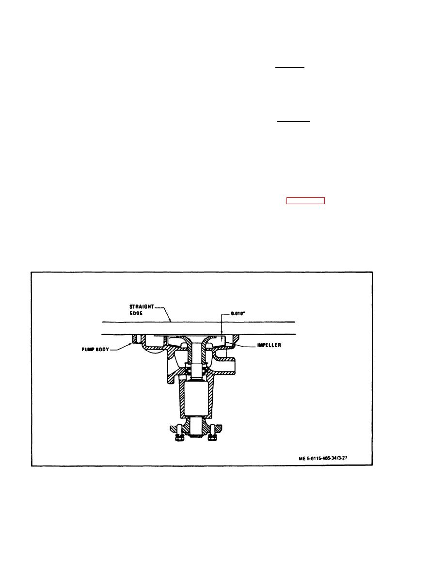
press impeller (10) onto shaft, bearing and flinger
assembly to obtain 0.010 inch clearance between
(6) Inspect shaft and bearing assembly for
impeller and cover plate (figure 3-27).
deep wear patterns, scores, pitting and other dam-
age. Rotate bearing on shaft. If bearing is binding
(4) Install gasket (8) and cover plate (7) and
or feels rough, the shaft and bearing assembly must
secure with screws (3). Install bracket (6) with screw
be replaced.
(4) and washer (5).
(7) Check impeller for erosion, cracking,
and other damage.
(5) Press pulley hub (1) onto shaft (9) until
shaft is flush with front of pulley.
(8) Replace any damaged or defective parts.
Figure 3-27.
Checking Impeller to Cover Plate Clearance
3-44


