TM 5-6115-465-34
TO35C2-3-446-2
NAVFAC P-8-625-34
TM06858B/06859D-34
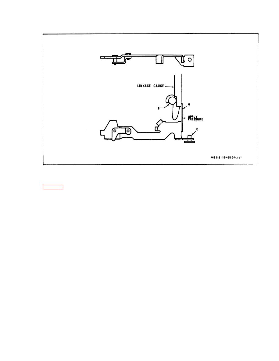
Throttle Linkage Adjustment
Figure 3-21.
bearing, Install high pressure injection Lines using
(50) Install new insulating tubes (11 and 12,
new gaskets. Leave fuel line connector screws at
pump and injection line nuts at the nozzles loose.
sulating washers (10), contact washers (9), and lock-
Install fuel inlet and return lines. Install transfer
nuts (8).
pump pressure gauge with a shutoff valve as close
to the transfer pump as possible.
(51) Install new gasket (6) to cover (4) and
secure cover to pump with flat washers (3), lock-
NOTE
washers (2) and screws (1).
f.
Fuel Injection Pump Bench Test.
Transfer pump pressure gauge must be
isolated by shutoff valve at the fuel in-
jection pump when checking fuel delivery
(1) General, The bench test procedure is
based on the following conditions:
and advance movement.
(a) Injection lines are 3/32 inch ID by 30
(b) Set counter and tachometer switches to
inches long.
clochwise position.
NOTE
(b) Fuel readings age based on fuel with
a viscosity of 34-36 SSU at 100 F.
Pump runs at half the engine speed.
(c) Fuel temperature at 110 to 115F.
(c) Start the test stand at lowest speed and
(d) Nozzles, part number 12SD12, adjust-
check for clockwise rotation. Move throttle to full-
ed to opening pressure of 2500 psi (170 ATS).
load position. When transfer pump picks up suction,
allow fuel to bleed for several seconds from loosen-
(2) Test procedure.
ed connector screws and injection line nuts, then
tighten securely.
(a) Mount pump securely in diesel injector
test stand using a suitable adapter. The drive adapter,
usually with a ball bearing, supports the shaft. This
(d) Operate pump at 500 rpm for 10 min-
pump must be tested with an intermediate support
utes. Dry off completely with compressed air.
3-35


