(3) Valve Bridge Installation.
(a) Install valve bridges in position on
bridge guide pins and valve stems.
(b) Install rocker arm assembly (para
b. Valve Bridle Guide Pins.
(1) Removal.
(a) Remove cylinder head from engine
(b) Remove valve bridge.
(c) Break bridge guide pin (fig. 54) off
as close to cylinder head as
possible, using a 1/2 inch pipe and
bending pin back and forth until it
breaks.
(d) Using a 5/16 inch drill, drill a hole
approximately 3/4 inch deep in the
center of portion of guide pin
remaining in cylinder head, then tap
the hole with a 3/8 inch NC tap.
Using a 3/8 inch NC
Figure 52. Removing valve lifter from bracket.
45. Valves, Bridges, Springs, Rotators, Guides, and
Seat Inserts
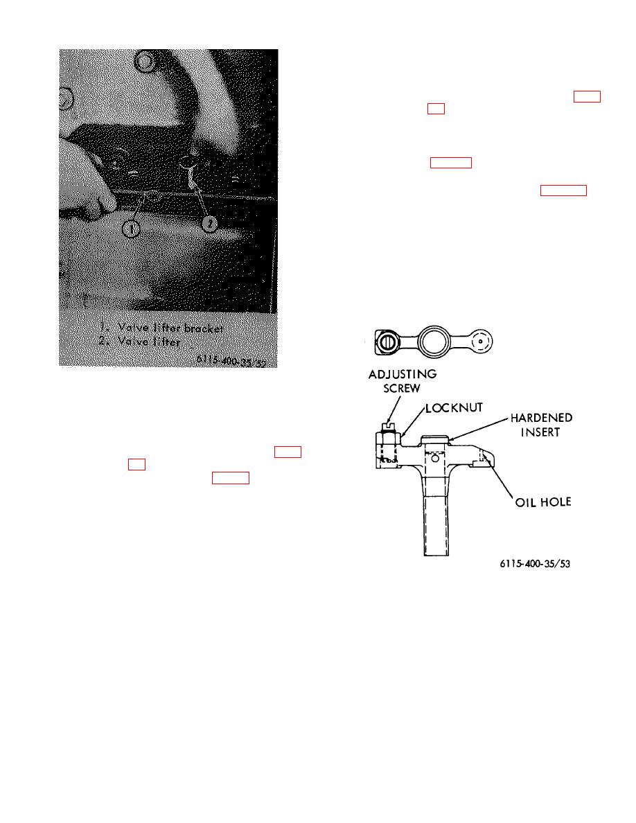
a. Valve Bridges.
(1) Removal.
(a) Remove rocker arm assembly (para
(b) Lift valve bridges (fig. 53) off bridge
guide pins.
(2) Cleaning and Inspection. Clean bridges in
a cleaning solvent. Using a wire, clean oil
hole located in end of cross member
opposite the adjusting screw. Inspect the
hardened insert in top of bridge for wear.
Replace insert if necessary.
The
specified bore in valve bridge guide is
.4995 inch-.5000 inch and specified O.D.
Figure 53. Valve bridge.
of bridge guide pin is .4970 inch-.4975
inch. If total clearance between bridge
and guide pin exceeds .006 inch, replace
bridge and/or guide pin. The bridge must
slide freely on guide pin.
89


