
TM 5-6115-400-12
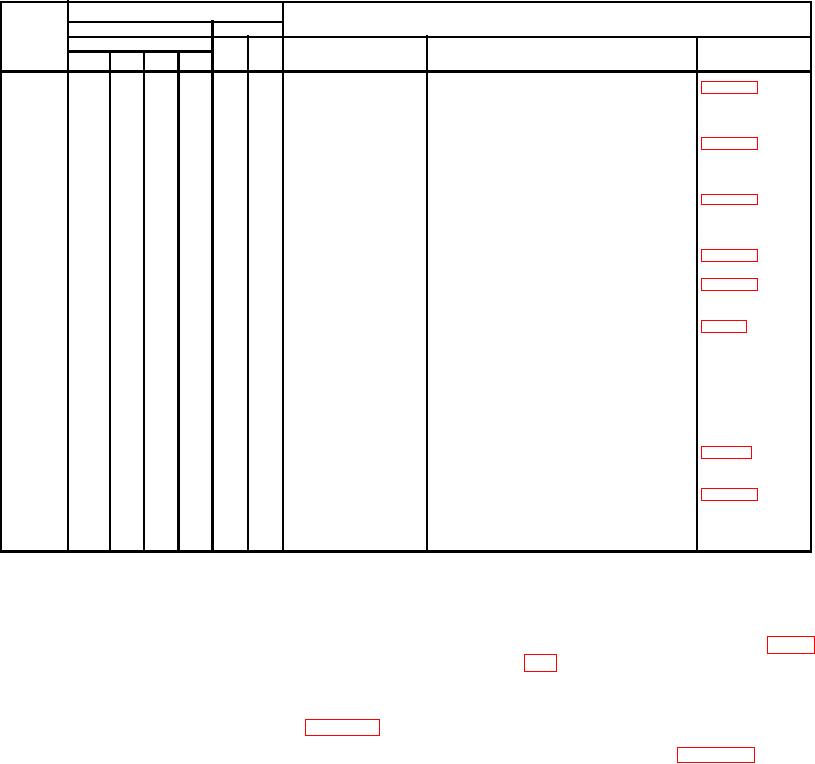
Table 3-2. Preventive Maintenance Checks and Services-Continued
Interval
B - Before operation
A - After operation
M - Monthly
Item
Operator
Org.
D - During operation
W - Weekly
Q - Quarterly
Number
Daily
B
D
A
W
M
Q
Item to be inspected
Procedure
Reference
8
*
*
Fire extinguisher
Check for broken seal. Weigh
new or charred extinguisher
4 ounce loss maximum.
4
*
*
*
*
Ground terminal
Check for adequate grounding.
5
*
*
*
Collector manifold
Open drain cock daily. Leave
open during shutdown period.
Drain cock MUST be closed
during engine operation.
6
*
*
*
Fuel tank
Fill as necessary. Clean cap
vent.
7
*
*
*
*
*
*
Oil level gage
Keep oil at "FOLD" on indicator.
Check current lubrication order.
8
*
*
*
Fuel filters
Drain sediment and water from
fuel filters.
9
*
*
*
Hydraulic tank
Check fluid level, add fluid as
required.
*
Inspect defective tank.
10
*
*
*
*
Batteries
Tighten loose connections. Re-
move corrosion. Check for
cracks and leaks. Fill to 3/8
inch above plates. Clean vent
holes in caps. Replace a
cracked battery.
11
*
*
Radiator
Coolant lever is 2 inches below
para 3-46
neck. Correct cap pressure
is 7 lbs.
12
*
Air cleaner
Check restriction indicator.
13
*
*
Vibration or noise
Be on alert for unusual noise
or excessive vibration.
14
*
*
Main generator
Check for frayed wiring. Clean
brushes and
or smooth dirty or rough slip-
sliprings.
rings. Replace brushes if worn
to 1/2 original size.
Section IV. OPERATOR'S MAINTENANCE
3-7. General
3-9. Fuel Tank
The instructions in this section are published for the
a. Fuel Tank Cap and Strainer.
information and guidance of the operator to maintain the
(1) Removal and Installation. Refer to figure
generator set.
3-3 and remove the fuel tank cap and
gasket and strainer.
3-8. Air Cleaner
b. Fuel Drains.
Check air restriction indicator daily. If red signal is
(1) Fuel drains are located at both corners of
visible, service the air cleaner as described in figure 3-2.
the fuel tank at the control panel end of
the generator set. See figure 3-4.
3-6