TM 9-6115-668-13
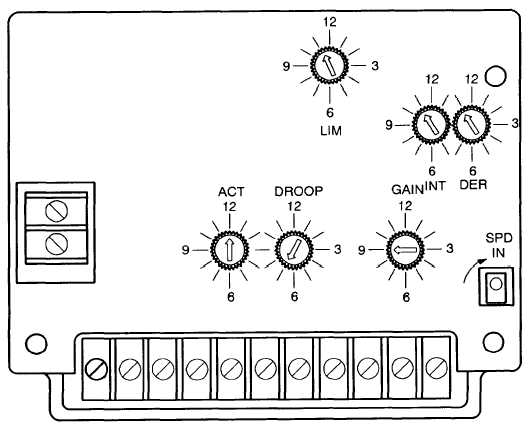
Figure 5-26 Speed Governor Assembly N1, Location of Potentiometers.
1.
2.
3.
4.
5.
6.
7.
Install speed governor assembly N1 (43) with mounting plate (51) and resistors R100 to R101 (50
to 57) on standoff (48) on back panel of control cabinet (3).
Install two screws (45) with two serrated lock washers (46) and two washers (47).
Connect cables (54) for resistors R100 to R102 (55 to 57) to connection strip (53).
Connect resistor R10 (41) to speed governor assembly N1 (43).
Noting correct labeling and position, reconnect cables to terminals (44) of speed governor assembly
N1 (43).
Swing digital isochronous load sharing module N4 (36) over speed governor assembly N1 (43).
Install two serrated lock washers (33) and two washers (34) and screw on two nuts (32) while hold-
ing standoffs (35).
8.
Stow prop (5) and close front panel (4).
9.
Close flap (2).
N O T E
Perform the ADJUSTMENT procedure when installing a new speed
governor assembly N1 (34).
5-119