TM 9-6115-668-13
h. Disconnect X/Y-printer from threaded pins of terminals L1, L2, L3 and N.
i. Install cover over socket terminals L1 to L3 and N in control cabinet as instructed in paragraph
5.24.
j. Disconnect load bank from Generator Set 150 kW.
Figure 5-28 Voltage Regulator N2, Location of Circuit Boards and Potentiometers.
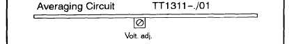
3. Adjust averaging circuit TT1311-./01:
a. Connect multimeter to terminals of VOLTAGE meter P6 (measurement range 300 V ~, Ri > 10
M ) .
b. Start up Generator Set 150 kW as instructed in paragraph 2.5.1.
5-123