TM 9-6115-660-13&P
TEST
1. Repeat removal step above.
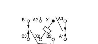
2. Refer to figure 5-16 and check continuity of relay coil between pins X1 and X2.
Figure 5-16. Relay K3-K6 Schematic.
WARNING
Dangerous voltage exits on live circuits. Always observe precautions and
never work alone. Failure to observe this warning could result in severe
personal injury or death.
3. Attach 24 VDC power source across pins X1 and X2 of relay and check continuity of relay contacts
before and after relay is energized as listed in table 5-4.
Table 5-4. Relay Operation
RELAY STATUS
CONTINUITY
BETWEEN PINS
Power NOT Applied
I
A2 and A3
B2 and B3
Power Applied
I
A1 and A2
B1 and B2
NO CONTINUITY
BETWEEN PINS
Al and A2
B1 and B2
A2 and A3
B2 and B3
4. If all multimeter indications are correct, perform installation procedures.
5. If any multimeter indication is not as listed in table 5-4 perform installation with new relay.
INSTALLATION
Install relay (3, figure 5-15) in relay socket (4) and secure with two washers (2) and screws (1).
5-27