ARMY TM 9-6115-604-12
NAVY NAVFAC P-8-633-12
4-84. INSPECT INTAKE AND EXHAUST MANIFOLDS AND SEALS. Intake and exhaust manifolds provide passage-
ways for air to enter and exit the engine.
a. Intake Manifolds. Two air Intake manifolds are bolted to the cylinder heads on each side of the engine On each
side, the two manifolds are joined by an air balance connector. A crossover housing also connects each manifold to
the aftercooler cover. Inspect the intake manifolds as follows:
(1) Carefully examine each air intake manifold (see Figure 3-3) air balance connection and crossover housing for
cracks or physical damage that could cause leaks. Refer all damages to the next higher level of maintenance.
(2) Inspect for air leaks or blown gaskets.
b.
Exhaust Manifolds. Two exhaust manifolds are used on the engine. Each manifold is a three piece assembly
consisting of two end sections and one center section. Inspect the exhaust manifolds as follows:
(1) Carefully examine each exhaust manifold (see Figure 3-3) for cracks or physical damage that could cause
leaks.
(2) With the engine running, carefully examine each manifold section, and the joints of each section, for evidence
of exhaust leakage.
4-85. INSPECT WATER TRANSFER TUBES. Water transfer tubes provide passageways for water to flow throughout
the cooling system. Each rocker lever housing is connected to a water transfer tube (see Figure 3-3). Inspect the water
transfer tubes as follows:
a.
Inspect for coolant leaks. Refer any leaks detected to the next higher level of maintenance
b.
With the engine running at normal operating temperature, check around each joint for evidence of coolant
leakage. Refer all leaks to the next higher level of maintenance
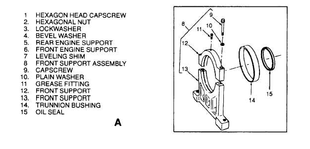
4-86. FRONT ENGINE SUPPORT. Inspect front engine support (6, Figure 4-61) for cracks or other defects that could
weaken the support.
Figure 4-61. Engine Assembly and Related Parts (Sheet 1 of 2)
4-154