ARMY TM 9-6115-604-12
NAVY NAVFAC P-8-633-12
(f)
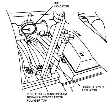
Using rocker lever actuator 3375010, move rocker lever until injector plunger is bottomed in cup (see Figure
4-57). This will remove oil from Injector that could cause a false indicator reading.
(g)
Allow the injector plunger to rise slowly to its fully extended position and bottom it again.
(h)
While holding the Injector plunger fully bottomed, set the dial indicator to zero.
(i)
Allow Injector plunger to rinse slowly to Its fully extended position, and remove actuator tool.
(j)
Using a torque wrench and torque wrench adapter ST-669, loosen locknut (Figure 4-56) and turn adjusting
screw to give a dial indicator reading of 0.308 ± 0.001 inch (7 82 + 0.03 mm). Maintain indicator reading while
tightening locknut to a torque of 30 to 35 pound-feet (41 to 47 newton-meters).
Figure 4-57. Bottom Injector Plunger
NOTE
If adapter ST-669 is not used, hold adjusting screw with screwdriver, and tighten locknut to a
true torque of 40 to 45 pound-feet (54 to 61 newton-meters).
(k) Use actuator tool and actuate plunger several times to recheck adjustment Dial indicator must indicate a reading
of 0.308 i 0 001 inch (7 82 ± 0.03 mm) as before.
(3) Adjustment of Valve Crossheads.
NOTE
Do not turn engine Complete the valve crosshead and valve rocker lever adjustments on the
cylinder selected for Injector plunger adjustment before turning engine to next set of VS marks.
(a) Loosen the adjusting nut (3, Figure 4-52) and back off adjusting screw (4) one complete turn.
4-149


