ARMY TM 9-6115-604-12
NAVY NAVFAC P-8-633-12
(b) Using light finger pressure at the rocker lever contact surface, hold valve crosshead (1) in contact with
valve (5).
(c) Tighten adjusting screw (4) until it just contacts valve stem (6).
(d) Using torque wrench adapter ST-669 hold adjusting screw in position and tighten nut (3) to a torque of 22
to 26 pound-feet (30 to 355 newton-meters).
NOTE
If adapter ST-669 is not used, hold adjusting screw with screwdriver and tighten locknut to a true
torque of 25 to 35 pound-feet (34 to 47 newton-meters).
(e) Using a wire gage, check the clearance between helical compress set (7) and valve crosshead (1)
clearance. Clearance A must be a minimum of 0 025 Inch (0.64 mm). If clearance A Is incorrect, refer to
the next higher level of maintenance.
(4) Adjustment of Valve Rocker Levers
NOTE
Ensure valve crossheads are adjusted in accordance with step (3), above, before adjusting valve
rocker levers. The exhaust valves for the left bank are located at the front of each cylinder head
The exhaust valves for the right bank are located at the rear of each cylinder head.
(a) Loosen the rocker lever adjusting screw locknuts. Using a feeler gage, adjust the clearance between the
contact surfaces of the rocker lever and crossheads to 0.014 inch (0.36 mm) Intake clearance, and 0 027
inch (0.69 mm) exhaust clearance (Figure 4-58).
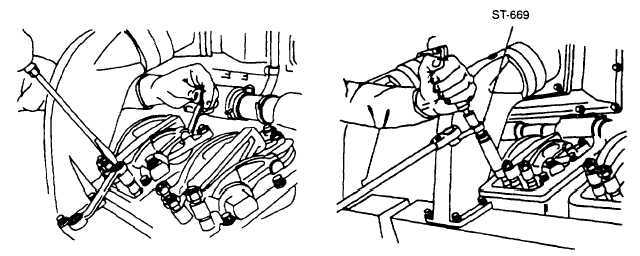
(b) Using a torque wrench and adapter ST-669 (Figure 4-59), hold adjusting screw in position and tighten
locknut to a torque of 30 to 35 pound-feet (41 to 47 newton-meters).
Figure 4-58. Adjusting Valve Rocker
Figure 4-59. Tightening Rocker Lever
Lever Clearance
Adjusting Screw Locknuts
NOTE
If adapter ST-669 is not used, hold adjusting screw with screwdriver and tighten locknut to a true
torque of 40 to 45 pound-feet (54 to 61 newton-meters).
(c) To be sure clearance has not changed due to tightening the locknut, recheck clearance In accordance with
step (a), above.
(5) Turn the engine to the next set of VS marks in the firing order (Figure 4-53), and carry out the adjustments on
that cylinder in accordance with steps (2), (3), and (4), above Repeat this procedure until the rocker levers on
all 12 cylinders have been adjusted.
4-150