ARMY TM 9-6115-604-12
NAVY NAVFAC P-8-633-12
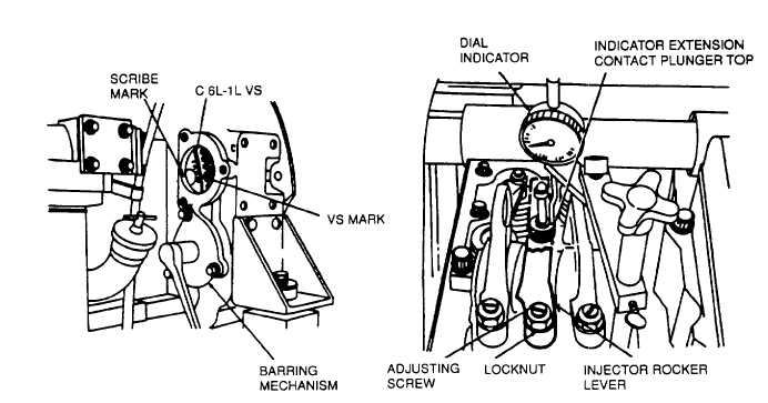
Figure 4-55. Flywheel Timing Marks
Figure 4-56. Dial Indicator Setup,
Injector Timing
NOTE
Two sets of VS marks are provided on the flywheel. those preceded by the letter A are used
when viewing from the right bank side of the flywheel housing, those preceded by the letter C are
used when viewing from the left bank side of the flywheel housing (Figure 4-54) Because both
starter motors are installed on the right bank flywheel housing, the VS marks preceded by the
letter A will not be used When using flywheel VS marks for valve and Injector adjustment, align
the marks at the left flywheel housing, and use only those marks pre- ceded by the letter C.
(2) Adjustment of Injector Plungers
(a) Remove the rocker housing covers In accordance with paragraph 3-14.
(b) Align one of the VS marks on the vibration damper with the pointer (Figure 4-54) or, when using the
barring mechanism to turn the engine, remove the access cover and align one of the VS marks with the
scribe mark on the left bank side of the flywheel housing (Figure 4-55).
(c) Determine which of the two cylinders indicated is to be adjusted by checking the valve rocker levers for
clearance. Clearance at the valve rocker levers denotes the cylinder to be adjusted.
(d) Attach the dial Indicator support and dial indicator, from tool set 3375004, to rocker housing of cylinder to
be adjusted. Ensure indicator extension is tight in indicator stem (see Figure 4-56).
NOTE
Ensure that the dial indicator extension remains In contact with the Injector plunger at all times
during the checking procedure. Do not allow the dial indicator extension to rub against the
rocker levers.
(e) With indicator extension resting on Injector plunger top, load indicator to a dial reading of approximately
0.325 inch (8.26 mm).
4-148