TM5-6115-634-14&P
NAVFAC P-8-647-14&P
T0-35C2-3-445-14
TM-6115-14&P/1
5-22.
REPAIR THE REMOTE FUNCTIONS BOX ASSEMBLY (cont)
f. The ohmmeter on M2 should drop
to O indicating a closed cir-
cuit.
Replace the relay if
this reading is not shown.
g.
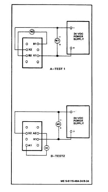
Change the test setup to test
two as shown in the figure.
h.
Repeat steps (c) through (f).
i.
Readings on M2 should be the
same as test one; if not,
replace the relay.
j.
Repeat steps (b) through (i)
for four remaining relays.
REPAIR
REPAIR THE REMOTE FUNCTIONS BOX
ASSEMBLY.
Repair of the remote functions
box assembly is accomplished by
replacing any of the five
relays that is malfunctioning.
If relays are not mal-
functioning replace remote
functions box assembly.
REMOVAL
REMOVE THE REMOTE FUNCTIONS BOX
ASSEMBLY.
a.
Refer to para. 5-19 and para.
5-20 and remove connectors
J29A and J29B.
b.
Remove four nuts (5), lock-
washers (6), flat washers (8)
and screws (7).
c.
Lift the remote functions box
assembly (9) from the mounting
bracket (10).
5-35

