TM5-6115-634-14&P
NAVFAC P-8-647-14&P
T0-35C2-3-445-14
TM-6115-14&P/1
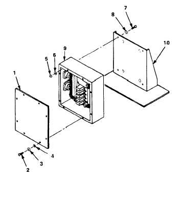
MAINTENANCE OF THE REMOTE FUNCTIONS BOX ASSEMBLY
5-22.
REPAIR THE REMOTE FUNCTIONS BOX ASSEMBLY
This task covers: a. Test
c. Removal
b. Repair
d. Install
INITIAL SETUP
Tools
General Mechanic’s Tool Kit
5180-00-177-7033
#1 Common Tool Kit
TBD
Multimeter
6625-01-139-2512 (2 ea)
Materials/Parts
Relay
96906-M5757/23-O03
Equipment Conditions:
Reference
Para. 4-9 General Instructions.
General Safety Instructions
NOTE
Two tests are required to determine
serviceability of the relays. A
24 Vdc adjustable power supply and
two multimeters are required to test
the relay.
TEST
TEST THE REMOTE FUNCTIONS BOX
RELAY.
a.
Remove the remote functions box
cover (1) by removing eight
screws (2), lockwashers (3) and
flat washers (4).
b.
c.
d.
e.
5-34
Set up an electric relay for
testing as shown in test one.
Adjust voltage on the power
supply between +1.5 Vdc and
+7.0 Vdc.
The ohmmeter on M2 should read
infinity indicating an open
circuit.
Replace the relay if
this reading is not shown.
Increase voltage on the power
supply to +18 Vdc.