TM5-6115-634-14&P
NAVFAC P-8-647-14&P
T0-35C2-3-445-14
TM-6115-14&P/1
MAINTENANCE OF THE WIRING HARNESSES
5-19. TEST AND REPLACE SPECIAL RELAY ASSEMBLY TO REMOTE FUNCTIONS BOX
ASSEMBLY WIRING HARNESS
This task covers: a. Removal
c. Repair
b. Test
d. Installation
INITIAL SETUP
Tools
Equipment Conditions:
Reference
General Mechanic’s Tool Kit
Para. 4-9 General Instructions.
5180-00-177-7033
Multimeter
General Safety Instructions
6625-01-139-2512
Materials/Parts
To avoid short circuits which could
Wiring Harness
damage equipment or injure personnel,
97403-13228E1911
always disconnect negative battery
Connector, Plug
cable before performing maintenance
96906-MS31O6R24-28P
on the electrical system.
Connector Plug
96906-MS31O6R22-19P
Connector, Plug
96906-MS5086R145-6P
REMOVAL
REMOVE WIRING HARNESS BETWEEN
SPECIAL RELAY BOX AND REMOTE
FUNCTIONS BOX ASSEMBLY.
a.
b.
c.
5-26
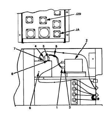
Remove connector P29A (1) from
the remote functions box
assembly (2) at J29A (3).
Remove connector P29 (4) and
PA (5) from the special relay
box (6) at J29 (7) and JA (8).
Remove the wiring harness (9)
from the generator set.