TM5-6115-634-14&P
NAVFAC P-8-647-14&P
T0-35C2-3-445-14
TM-6115-14&P/1
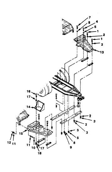
4-42. REPLACE FRONT STEP, CURBSIDE AND ROADSIDE (cont)
2.
d. Remove seven 1-inch screws
(10), 14 flat washers (11) and
seven self-locking nuts (12)
and remove roadside front step
(13).
REMOVE FRONT STEP CURBSIDE.
a. Remove two gas can brackets (14)
from curbside front step (15) by
removing eight screws (16), 16
flat washers (17) and eight
self-locking nuts (18).
b.
Perform steps 1a through 1d
above to remove the curbside
front step (15).
INSTALLATION
1.
INSTALL FRONT STEP, ROADSIDE.
a.
Install roadside front step (13)
with four 1-3/4 inch screws (1),
eight flat washers (2) and four
self-locking nuts (3).
b.
Install seven 1-inch screws
(10), 14 flat washers (11) and
seven self-locking nuts (12).
c.
Install two 1-inch screws (4),
four flat washers (5) and
two self-locking nuts (6).
d.
Install 1-1/4 inch screw
(7), two flat washers (8)
and self-locking nut (9).
2.
INSTALL FRONT STEP, CURBSIDE.
a. Perform steps 2a through 2d,
above, to install the curbside
front step (15).
b.
Install gas can brackets (14) by
installing eight screws (16),
16 flat washers (17) and eight
self-locking nuts (18).
4-64