TM5-6115-593-34
NAVFAC P-8-631-34
TO-35C2-3-463-2
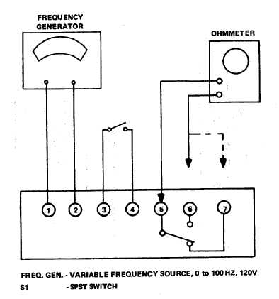
Figure 15-11. Underfrequency and Overfrequency-Relay, Test Setup
(5) Decrease frequency generator frequency
to 58. 2 Hz. With ohmmeter connected
between terminals 5 and 6, relay should
trip at 58. 2 Hz (57. 7 to 58. 7 Hz), at
which time ohmmeter will no longer
show continuity.
(6) Turn adjustment screw clockwise to raise
trip point.
b. Replacement. The underfrequency relay (10,
figure 15-9) is removed and replaced a follows:
(1) Disconnect and tag wires connected to
the underfrequency terminal board.
(2) Remove four screws and washers.
Remove device (10) from panel (7).
(3) Replace underfrequency relay (10) by
attaching to panel (7) with four screws
and washers. Connect wires and
remove tags.
15-18. OVERFREQUENCY RELAY. The overfrequency
relay (9,. figure 15-9) is adjustable within the range
specified in the tabulated data in Chapter 1 of the
Operator and Organizational Maintenance manual. Trip
setting is adjusted with the adjustment screw on the
device. Test the device as follows: a. Test.
(1) Connect overfrequency relay as shown in
figure 15-11.
(2) Adjust variable frequency generator for
50. 0 Hz output. Close switch SI.
(3) With ohmmeter connected between
terminals 5 and 7, adjust frequency
generator to 51. 5 Hz (51 to 52). At
this point, relay should trip. Ohmmeter
will no longer show continuity.
15-16


