TM5-6115-593-34
NAVFAC P-8-631-34
TO-35C2-3-463-2
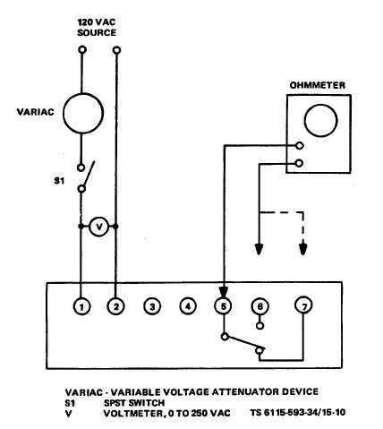
Figure 15-10. Under/Over Voltage Relay, Test Setup
Under/overvoltage relay (11, figure 15-9) is
removed as follows:
(1)
Disconnect
and
tag
wires
to
under/overvoltage
device
terminal
board.
(2) Remove four screws and washers.
Remove device.
(3) Replace under/overvoltage device by
attaching to panel with four screws and
washers. Connect wires and remove
tags.
15-17. UNDERFREQUENCY RELAY. (10, figure 15-9).
The device is adjustable within the range specified in the
tabulated data in Chapter 1 of the Operator and
Organizational Maintenance manual. Test numbers given
in the procedures below are nominal. Trip setting is
adjusted with the adjustment screw on the device. Test
and replace as follows:
a.
Test.
(1) Connect underfrequency relay as shown
in figure 15-11. Switch S1 closed.
(2) Adjust variable frequency generator for
50 Hz output.
(3) With ohmmeter connected between
terminals 5 and 7, adjust frequency
generator to 48.5 Hz. Relay should trip
as frequency is decreased. Ohmmeter
will no longer show continuity.
(4) Open switch S1. Adjust frequency
generator for 60 Hz output.
15-15


