TM5-6115-593-34
NAVFAC P-8-631-34
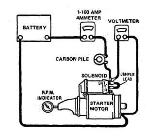
Figure 13-5. No Load Test Circuit (Code A)
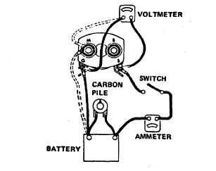
Figure 13-6. Checking Solenoid Hold-In and Pull-In
Windings (Code A)
CAUTION
Do not leave pull-in winding energized for more than
15 seconds.
(3)
To check the pull-in winding, connect the
other battery lead to the M terminal (shown in dotted line).
(4)
Adjust the voltage to 5 volts. Voltmeter
shall read 5V AC and ammeter shall read 10 to 11.5
amps.
TO-35C2-3-463-2
(5)
Replace switch if either winding is
shorted or shows excessive resistance.
j.
Repair. Repair of the starter motor consists of
repairing commutator bars whenever possible (if not
badly burnt) and replacement of parts found defective
during inspection. Repair commutator bars as
follows:
(1)
Using rosin flux, resolder or weld leads in the
riser bars.
(2)
Turn down the commutator in a lathe.
(3)
Undercut and clean the commutator as
indicated in paragraph k.
k. Overhaul. Overhaul of the starter motor consists of
overhauling the armature commutator and
replacement of parts found defective during
inspection. Overhaul the commutator as follows:
(1)
Turn down commutator in an appropriate
lathe.
(2)
Undercut the insulation 1/32 of an
inch wide and 1/32 of an inch deep.
Remove any trace of dirt or copper dust
between slots.
(3)
Sand the commutator lightly with
No. 00 sandpaper to remove any burrs
resulting from the undercutting procedure.
l.
Assembly. Assemble the motor in accordance with
figure 13-4.
(1)
Install the pole shoes (91) and secure with
pole shoe screws (90).
(2)
Install the armature (89) and field coil (99)
in the housing (104).
(3)
Install the lever housing (37) with screws
(26), and washers (27)..
(4)
Position the washer (34) and gasket (33) in
the lever housing and install the drive
assembly (25) in
13-10