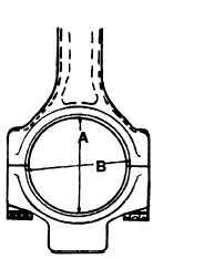
Figure 14-43. Conneting Rod, Crankshaft End
Avoid causing nicks and other physical damage
to the I-beam section of the connecting rod.
Do not clamp I-beam section of rod in a vise.
Whenever connecting rod is clamped in a vise,
use lead jaw protectors and clamp rod on the
crankshaft end only.
f. Measure outside diameter of the piston pinto
determine amount of wear. Outer diameter of a new pis-
ton pin is 1.5011 to 1.5013 inches. The bore of the con-
necting rod bushing is 1.5027 to 1.5032 inches. These
dimensions of pin and bushings provide a running clear-
ance of 0.0014 to 0.0021 inch. Replace the connecting rod
bushing if clearance exceeds 0.002 inch.
g. Inspect connecting rod for cracks by the mag-
netic particle wet fluorescent continuous method.
h. Magnetization must be performed longitudinally
(between the heads) using a minimum current of 2000
amperes and, transversely, (in the coil) using a minimum
current of 800 amperes. A minimum of two applications
of current of approximately one-half second duration in
each position should be made. Apply indicating solution
gently and uniformly to all portions of the part while the
magnetizing current is flowing.
i.
Inspect the threads of connecting rod and lock
bolts. If damaged, they must be replaced.
j.
Check the alignment, length and twist of connect-
ing rod, using a checking future. The checking fixture
must fist be calibrated as follows:
(1) Select a new connecting rod that has been
checked for correct nominal length of 8.500 inches. The
length of new connecting rod (center-to-center of bores)
is 8.498 to 8.502 inches.
(2) Lubricate threads of
connecting rod bolts
with engine oil and assemble cap to connecting rod.
Tighten bolts alternately to torque of 80-85 foot-pounds.
(3) Install pin and crank mandrels in connecting
rod. Center crank mandrel in crankshaft end so the
expanding pin is located in bottom of bore near the center
of rod cap. Tighten expanding pin snugly.
(4) Place rod with mandrels in checking future.
(5) Adjust dial indicators until their hands move
approximately on revolution while resting on pin mandrel.
(6) Adjust indicator faces to zero.
(7) Remove connecting rod and mandrels as an
assembly from checking fixture, turn rod horizontal y
180° and carefully place back in future. Readjust indica-
tor faces so the zero position is halfway between original
zero and reading and the new reading. The fixture is now
calibrated.
(8) Carefully remove connecting rod and man-
drels as an assembly from checking future.
k. Check connecting rod alignment as follows:
(1) Lubricate threads of connecting rod bolts
with engine oil and assemble cap to connecting rod that is
to be checked. Tighten bolts alternately to specified
torque of 80 to 85 foot-pounds for socket head capscrews
or 65 to 65.5 foot-pounds for 12 point capscrews.
(2) Install pin and crank mandrels in connecting
rod. Center crank mandrel in large bore so the expanding
pin is located in bottom of bore near the center of rod cap.
Tighten expanding pin snugly.
(3) Carefully place rod with mandrels in check-
ing fixture and record indicator readings.
(4) Remove connecting rod and mandrels as an
assembly from checking fixture; turn rod horizontally
180° and carefully replace in future. Record the new
indicator readings.
(5) The maximum allowable bend in the rod is
a combined total gauge reading of 0.004 inch. Calculate
the differences in the individual indicator gauge recorded
readings between step (3) and (4) above. Then add the
two to get the combined total gauge reading.
Change 12
14-89