REF DES
DESCRIPTION
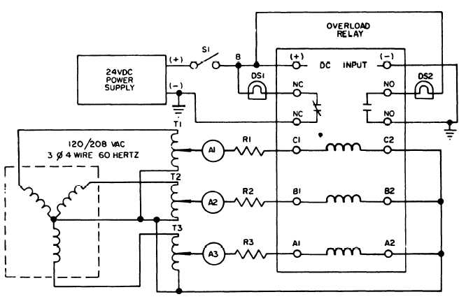
DS1 , DS2
R1, R2, R3
S1
Tl, T2, T3
Figure 8-11. Overload
(a) Connect an external switch across
terminals and 8. Close switch.
(b) Adjust the frequency to 50 Hz and the
input voltage to 120 volts. Relay contacts should
pick up; lamp DSl should light and DS2 should ex-
tinguish.
(c) Lower frequency slowly until relay con-
tacts drop out (lights transfer). Contacts should
drop out at 46 + 1 Hz.
—
(d) Raise frequency slowly until contacts
pick up (DS1 should light and DS2 should extinguish).
Contacts should pick up at 45 to 49 Hz.
(e) Raise voltage to 132 volts and check for
drop out lights transfer). Drop out should occur
within + 1 Hz of drop out at 120 volts.
(f) Lower voltage to 108 volts. Drop out
(lights transfer) should occur within ± 1 Hz of drop
out at 120 volts.
INDICATOR LIGHT
RESISTOR, FIXED
SWITCH, DC POWER
3 PHASE VARIAC
ME 6115-545-34/8-11 C1
Relay Test Set-Up
(g) Open switch between terminals 7 and 8,
and adjust input frequency to 60 Hz. Repeat steps
(b) through (f). Drop out should occur at 55 ± 1 Hz;
pick up at 58 + 1 Hz.
(3) To test the undervoltage relay, see figure
8-13 and refer to paragraph 8-7c (4), but adjust
frequency for 50/60 Hz operation.
(4) To test the permissive parallel relay,
perform the procedure in paragraph 8-7c (6), but
adjust frequency for 50/60 Hz operation.
(4a) To test the resistor assembly (A6), refer
to figure 1-7 and proceed as follows:
(a) Check the resistance of R4 between
points 1 and 2 on terminal board TB1 06. Resistance
should be 250 ohms.
(b) Check the resistance of R5 between
points 3 and 4 on terminal board TB106. Resistance
should be 250 ohms.
Change 1 8-17