ME 6115-545-34/8-14 C1
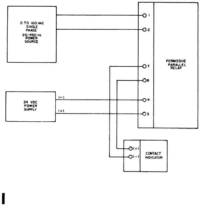
Figure 8-14. Permissive Parallel Relay Test Set-Up
(7e) To test shunt (R13), apply 20 amperes
(3) If any connections are opened or bared
to input of shunt and measure output with a milli-
for test purposes, or if any defective components
voltmeter. Output should be 50 millivolts.
are replaced the effected area and component must
be coated with polyurethane resin to prevent oxida-
(8) Make a point-to-point check of all wiring
tion or other corrosion. The coating must be of a
and chassis mounted components. (See schematic
diagrams in Chapter 1.)
minimum thickness of 0.007 inches and air bubble
entry into the applied polyurethane must be con-
trolled so that the legibility of component coding
8-8. Repair, Reassembly, and Installation.
and identification is not impaired.
a. Repair.
(1) Replace
during testing.
(2) Replace
and transformers.
8-20 Change 1
(4) Replace defective connectors.
any relay found to be defective
(5) Repair or rebuild wiring harnesses as
required. See wiring schematics in Chapter 1 and
wiring harness diagrams in Chapter 5.
all defective diodes, resistors,