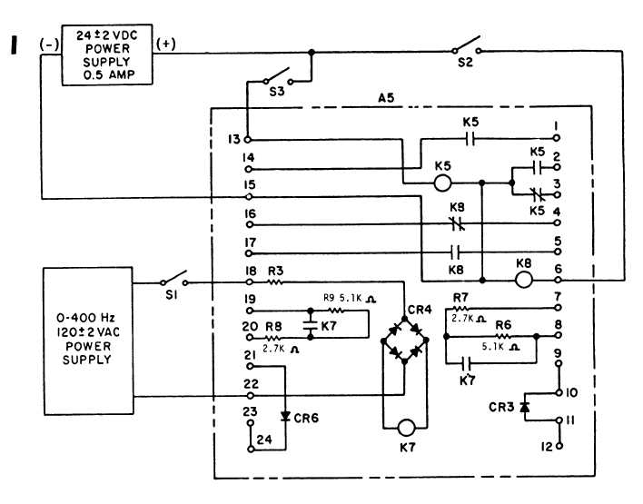
Figure 8-13A. DC Relay Assembly (A5) Test Setup
(d) Connect 24 vdc across terminal 6 (+)
(6) TO test the permissive parallel relay (K16) (Mode
and 15 (—) and close S2 switch. There shouldn‘t be con-
11 Sets), see figure 8-14 and test as follows:
tinuity between terminals 4 and 16, and there should be
continuity between terminals 5 and 17. If this is not ob-
(a) Apply 24 vdc to terminals 3 (+) and 4
tained, check for defective relay K8.
(–).
(e) Remove 24 vdc from terminals 6 and 15
(b) Apply 20 volts, 400 Hz across terminals
and connect across terminals 13 and 15 and close S3
1 and 2.
switch. Measured voltage between terminals 3 and 15
should be 24 vdc; zero between terminals 3 and 13. Con-
(c) Normally open contacts 5 and 6, and
tinuity should exist between terminals 1 and 14 and 2
normally closed contacts 7 and 8 must transfer.
and 15. If these readings are not obtained, check for
defective relay K5.
8-18B
Change 10