TO
35C2-3-442-2
P-8-627-34
TM 5-6115-457-34
TM-07464A-35
Section XIII. HYDRAULIC PUMP (PRECISE SETS ONLY)
3.
Bolt (4)
GENERAL.
8-93.
4.
Washer (4)
5.
Gasket
The hydraulic pump is mounted to
6.
Coupling shaft
the hydraulic pump drive group and is
7.
Fitting (2)
driven through the camshaft gear. The
8.
Pump assembly
hydraulic pump is used on precise genera-
tor sets only. The hydraulic pump is a
b. When removing pump assembly (8)
positive displacement gear type pump with
from pump drive, hold hand under adapter
a built in adjustable relief valve. The pump
flange on pump drive to catch coupling
is coupled to the pump drive group by means
shaft (6) when it drops out.
of a tang type drive coupling. The pump
I
WARNING
consists of a shaft, dual gears, sleeve
bearing and seal.
Cleaning Solvents are flammable and
moderately toxic to skin, eyes and
8 - 9 4 . REMOVAL.
respiratory tract. Eye and skin
protection required. Good general
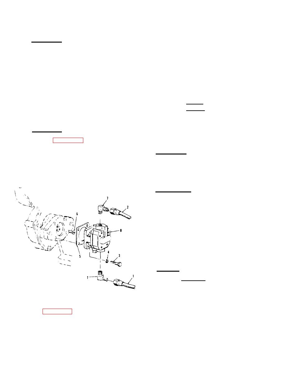
Refer to figure 8-23 and remove
ventilation is normally adequate.
hydraulic pump in the order of index numb-
CLEANING.
8-95.
e r s assigned. Pay particular attention to
the following.
Wash pump assembly in an approved
a. Disconnect hose assemblies (1 and 2)
solvent to remove grease, and hydraulic
from pump suction and discharge ports, and
fluid residue. Dry with a lint free cloth.
plug hose assemblies to prevent fluid spil-
lage.
8-96. INSPECTION.
a. Check pump shaft for freedom of
rotation.
b. Inspect coupling shaft (6) for nicks
and burrs on tang end.
c. Inspect condition of threaded holes
in suction and discharge ports.
d. Discard gasket.
REPAIR.
8-97.
CAUTION
Do not use a grinding wheel on
coupling shaft tang.
Figure 8-23. Hydraulic pump, exploded
view (precise sets only)
a. Remove nicks and burrs on drive
Legend to figure 8-23:
tang of coupling shaft using a suitable
1. Hose assembly (suction)
file.
2. Hose assembly (discharge)
8-48
Change 8


