P-9-TM-457-35 T.O. 35C2-3-442-2
TM-07464A-35 TM 5-6115-457-34
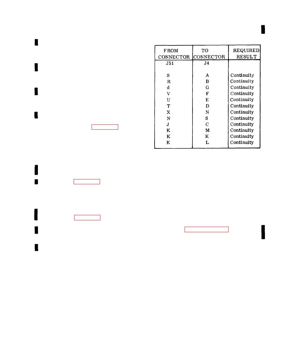
Table 6-16. Tactical Relay Box (A29)
1. To isolate a malfunction of the
Continuity Test
overvoltage relay, refer to paragraph
6-163.
2. To isolate a malfunction of the
reverse power relay, refer to paragraph
6-167.
3. To isolate a malfunction of the
short circuit relay, refer to paragraph
6-171.
4. To isolate a malfunction of the
overload relay, refer to paragraph
6-175.
b. Removal. Refer to figure 6-15, dis-
connect the two electrical plug connectors
at the tactical relay box receptacles, then
remove the two screws and washers secur-
ing the box in position. Remove the tactical
relay box.
a. Tag, then disconnect harness wiring
from components.
6-180. BENCH TEST.
b. Remove overvoltage relay (K2),
a. Refer to table 6-16 and perform a
continuity test of the tactical relay box.
overload relay K14), short circuit relay
(K13) and reverse power relay (K15) from
b. Connect the tactical relay box to
the chassis by removing their attaching
screw assemblies (4 each),
test equipment as illustrated in figure
6-46 and perform test specified in proce-
NOTE
dural analysis table 6-17.
Refer to paragraphs 6-162, 6-174,
6-181. DISASSEMBLY. Disassemble the
tactical relay box to the extent necessary
6-170, and 6-166 respectively for
relay maintenance instructions.
to accomplish repair. Refer to figures
6-41 and 6-47 and disassemble in the order
of index numbers assigned. Pay particular
c. Remove terminal board (TB2), gov-
attention to the following.
ernor resistor assembly (19), and mount-
ing bracket (30) as an assembly by remov-
NOTE
ing screw assembly (29).
d. Remove the wire harness (6) from
Remove the four screws and washers
securing the cover to the relay
the chassis by removing eight screw as-
chassis.
semblies (2 and 3) and nuts (4 and 5).
6-135/(6-136 blank)
Change 3


