
TO 35C2-3-442-2
meter leads and continue lowering the speed.
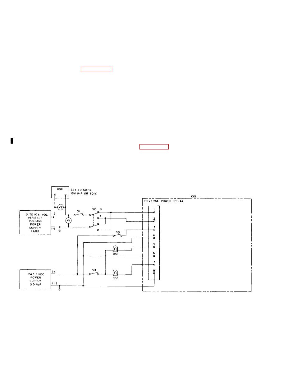
c. Set Oscillator to 60 hertz, 10VAC
(peak to peak). Close switch S1 and set
Relay K15 should actuate when the voltage is
S2 to position "A". Increase variable
2 0.1 VDC, 50/60 hertz sets; 5 0.1 VDC,
voltage DC power supply to 10VDC, then
400 hertz sets, and terminal 1 is positive.
return to VDC. Indicator DS2 should
If the relay does not actuate under the pre-
remain energized and DS1 should remain
ceding conditions, replace the relay.
deenergized.
b. Removal. Refer to figure 1-19 and
6-41 and tag, then disconnect wiring from
d. Set switch S2 to position "B". Increase
the reverse power relay. Remove the four
variable DC voltage slowly. Indicator DS2
screw assemblies securing the relay in
should deenergize and DS1 energize at 2 VDC,
position.
50/60 hertz sets; 5 VDC, 400 hertz sets or
less.
6-168. BENCH TEST.
e . If the reverse power relay does not
a. Connect the reverse power relay to
the test equipment as illustrated in figure
meet the requirement of the above tests, re-
6-43.
place the relay.
b. Energize 24VDC power supply and
f. Remove the reverse power relay
close switches S4 and S3. Indicator DS2
from the test equipment. Reference
should be energized and DS1 should be
deenergized.
Figure 6-43. Reverse power relay (K15) test setup
Change 11
6-130
