P-9-TM-457-35
T.O. 35C2-3-442-2
TM-07464A-35
TM 5-6115-457-34
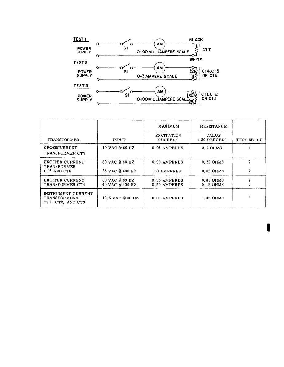
Figure 6-40. Transformer inspection
a. Connect transformer assembly (9) to
NOTE
generator and secure with spacers (2),
screws (7), and lock washers (6 and 8).
Interconnecting wiring diagram is
contained in Operator and Organi-
b. Refer to Operator and Organizational
zational Maintenance Manual.
Maintenance Manual and route six gene rater
leads through transformers. Leads pass-
d. Connect electrical wiring to trans-
ing through transformers CT4, CT5, and
formers and terminal board.
CT6 make two turns around transformers.
c. Connect generator leads to recon-
e. Position shield over transformer
nection board studs. Secure leads together
assembly and secure with screws (1),
with tie straps.
lock washers (2) and washers (3).
Change 3
6-125


