P-9-TM-457-35 T.O. 35C2-3-442-2
TM-07464A-35 TM 5-6115-457-34
NOTE
6-165. INSTALLATION. Refer to figure
6-41 and install the over voltage relay
Remove cover from tactical relay
in position using four screw assemblies.
box to gain access to test points,
Refer to figure 1-19 and reconnect wiring.
see figures 6-15, 6-41, 6-43 and
Replace the tactical relay box and cover.
6-166. REVERSE POWER RELAY (K15).
1. Operate the generator set in
parallel with another like unit.
6-167. ON EQUIPMENT TEST.
a. Symptom and Isolation of Malfunc-
2. Adjust voltage and frequency to
tion. A malfunction of the reverse power
rated value and mea sure the voltage across
relay K15 is usually indicated by failure
terminals 3 and 4 of relay K15. In addi-
of the generator fault monitoring system
tion, measure the voltage from TB2-5 to
to detect and react to a reverse power con-
K 15 relay terminals 5 and 8. Voltage
dition when operating two or more generator
should be 20-32 VDC at all points.
sets in parallel. To isolate the malfunc-
tion, proceed as follows.
3. Slowly reduce the generator
WARNING
set (unit under test) speed while monitor-
ing the voltage across terminals 1 and 2
Exercise extreme care not to touch
of relay K 15 (approximately 9.8 VDC,
exposed electrical connections when
working inside tactical relay box with
terminal 2 positive, at 100 percent load).
When the voltage is zero, reverse the
generator set operating.
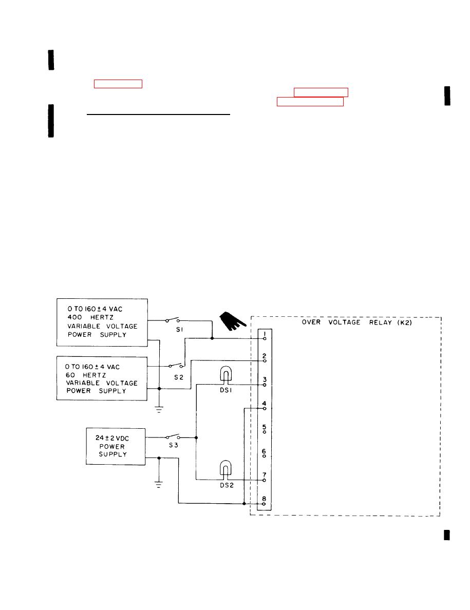
Figure 6-42. Over voltage relay (K2), test setup
6-129
Change 3


