T O 35C2-3-442-2
P-8-627-34
TM 5-6115-457-34
TM-07464A-35
b. Repair printed circuits by soldering
a jumper wire across defective area.
Replace all defective components.
c.
d. Solder replacement components
using solder conforming to Federal Speci-
fication QQ-S-571 Sn 60.
6-21. REASSEMBLY.
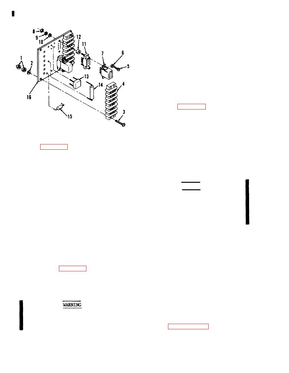
Refer to figure 6-4 and reassemble
control box relay assembly in reverse
order of index numbers assigned. Pay
particular attention to the following.
Figure 6-4. Control box relay assem-
a. When replacing soldered compon-
bly, exploded view
ents, use a suitable heat sink. Solder
Legend to figure 6-4:
joints and/or component leads shall not
10. Lock washer (4)
1. Nut (8)
project more than 0.094 inch beyond the
11. Relay socket (2)
2. Washer (4)
surface of the board.
1 2 . Spacer
3. Screw (4)
1 3 . Silicone bridge
4 . Terminal
rectifier
board (2)
14. F i x e d resistor
5. Screw (4)
WARNING
15. Capacitor
6. Washer (4)
1 6 . Terminal board
Insulating Compound, MIL-I-46058 is
7. Relay (2)
flamable and slightly toxic to eyes,
8. Nut (4)
skin and respiratory tract. Eye and
9. Washer (4)
skin protection required. Good gen-
c. Check resistor for proper ohmic
eral ventilation is normally adequate.
value. (15 K Ohms.)
d. Check capacitor for proper capaci-
b. Spray or brush a conformal coating,
tance value.
0.005 inch thick, of a transparent dielec-
e. Inspect relay sockets for cracked
tric compound corresponding to Specifica-
insulation and broken pin receptacles.
tion MIL-I-46058, Grade S, Type PUR to
f. Test plug in relays for actuation
the assembly.
as illustrated in figure 6-5.
NOTE
6 - 2 0 . REPAIR.
a . Restencil illegible reference desig-
The compound shall securely anchor
nations.
the components to the terminal
board. Terminals for connection to
external circuits shall not be coated.
Avoid breathing fumes generated by
c. Test control box relay assembly as
unsoldering/soldering. Eye pro-
outlined in paragraph 6-16.
tection is required.
Change 8
6-8


