T.O. 35C2-3-442-2
P-9-TM-457-35
TM 5-6115-457-34
TM-07464A-35
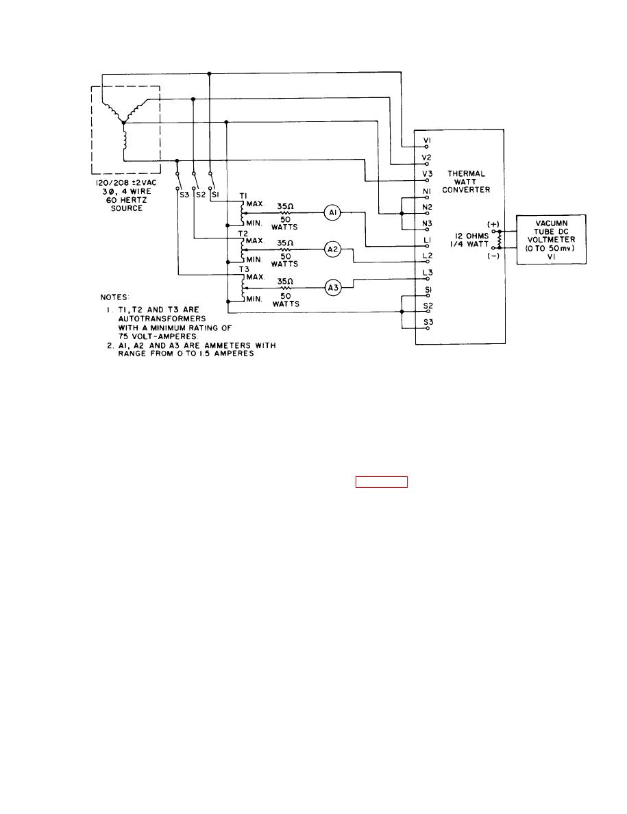
Figure 6-1. Thermal watt converter (Al) test setup
scale, high or low readings with the fre-
Voltage should be 120 10 percent vac, if
quency adjusting controls set in their nor-
not check wiring back to voltage source.
mal positions. To isolate the malfunction,
4. Connect a test frequency meter
proceed as follows:
1. Loosen three captive studs and
or generator output terminal. Check panel
hinge control box door open.
frequency meter accuracy against test
meter while varying engine speed using
2. Start generator set and apply
manual speed control on utility generator
load.
sets or frequency adjust rheostat on pre-
cise generator sets. If meters do not in-
dicate the same, replace frequency meter
WARNING
and transducer.
Exercise extreme care not to touch
b. Removal. Refer to Operator and
exposed electrical connections when
Organizational Maintenance Manual and
working inside control cubicle with
remove the frequency meter and transducer.
generator set operating.
6-10. CLEANING. Clean the frequency
3. Measure input voltage to fre-
meter and transducer using a clean lint-
quency transducer (A2) at terminal 1 and 2.
6-3


