P-9-TM-457-35
T.O. 35C2-3-442-2
TM-07464A-35
TM 5-6115-457-34
free cloth, moistened with unapproved
cleaning solvent and dry thoroughly.
6-11. INSPECTION. Inspect the frequency
meter and transducer cases for cracks or
tears and the electrical connectors for bent
pins and insulation breakdown.
6-12.
TEST.
NOTE
The frequency meter and transducer
are a matched set and must be tested
as a set.
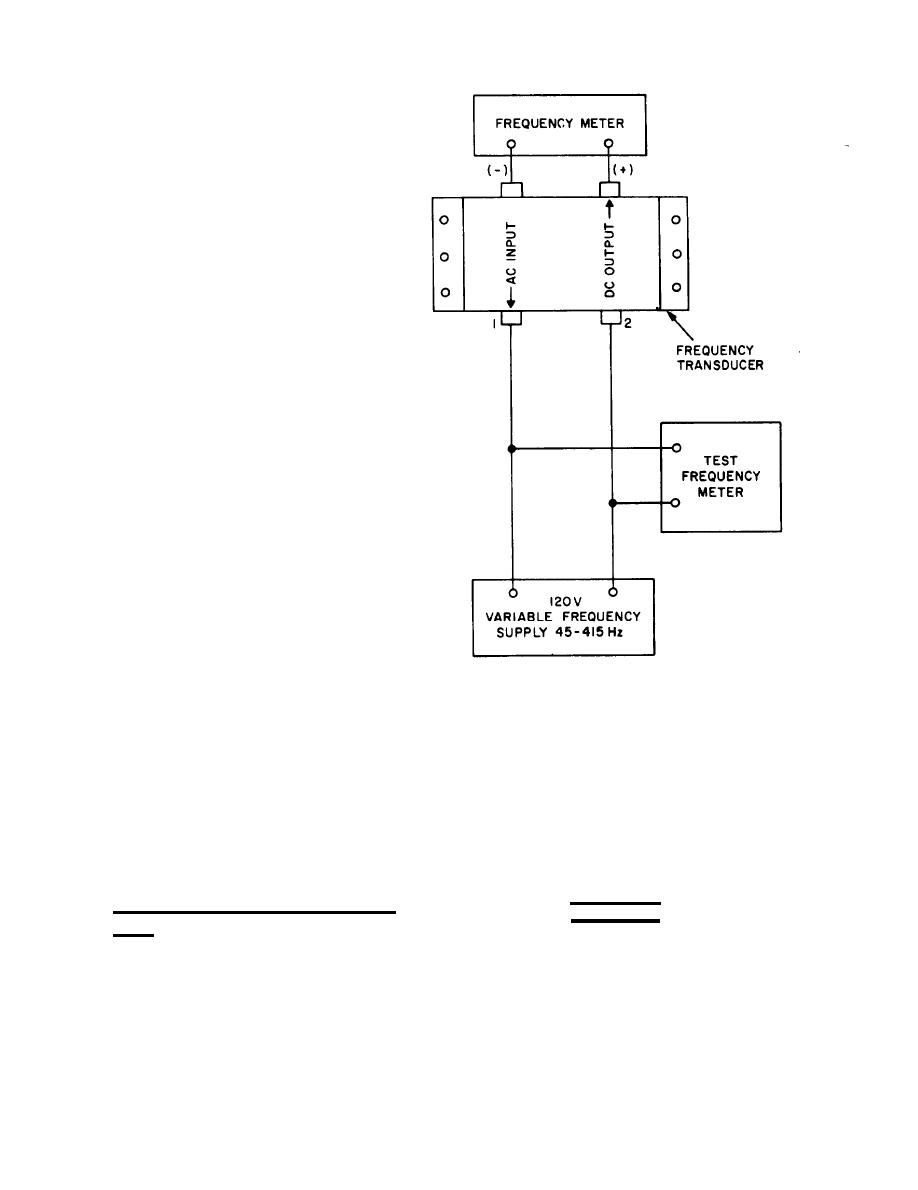
a. Connect a variable frequency 120
VAC frequency generator to the AC side of
the frequency transducer as shown in figure
6-2.
b. Connect a reference frequency meter
across the input. The master frequency
meter shall have 5 times the accuracy of
the set frequency meter and transducer
(1/20 of 1 percent).
c. Vary the frequency from lowest
scale reading to full scale reading.
d. The error at any point on frequency
Figure 6-2. Frequency meter (M6) &
meter shall not be greater than 1/4 of 1
transducer (A2) test setup
percent.
relay assembly (A4) is usually indicated by
failure of the generator set to run when the
e. Remove test equipment. Replace
start- run-stop switch (S2) is positioned to
defective frequency meter and transducer.
RUN or by inability to control voltage from
a remote location. To isolate the mal-
6-13. INSTALLATION. Refer to Operator
function proceed as follows:
and Organizational Maintenance Manual
and install the frequency meter and trans-
1. Loosen three captive studs and
ducer.
hinge control box door open.
CONTROL BOX RELAY ASSEMBLY
6-14.
WARNING
(A4).
Exercise extreme care not to touch
TEST ON EQUIPMENT.
6-15.
exposed electrical connections when
working inside control cubicle with
a. Symptoms and Isolation of Malfunc-
generator set operating.
tion. A malfunction of the control box
6-4


