TM 5-6115-400-35
1.
Crankshaft
2.
Cylinder sleeve puller shoe
3.
Cylinder sleeve
4.
Shoe centering cone
5.
Puller rod
6115-400-35/102
Figure 108. Removing cylinder sleeve-bottom view.
(refer to following para d). The special sleeve tool,
shown in figure 103, is made from a new
cylinder sleeve. The sleeve is machined as
follows to assure proper relationship between
the lower surface of the sleeve flange and the
sleeve center line.
(a) Place the flange end of a new sleeve in
the chuck of a lathe.
(b) True the center line of the sleeve as
closely as possible to the lathe center by
using dial indicators at each end of the
sleeve.
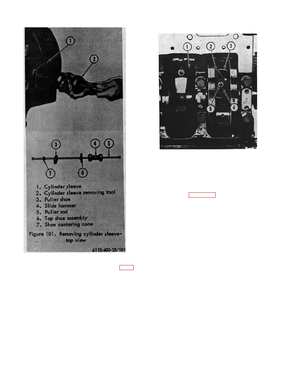
Figure 101. Removing cylinder sleeve-top view.
the bottom of the counterbore as shown in figure
103. Total indicator reading should not exceed
.002 inch. If the total dial indicator reading
exceeds the specified limit, reworking the
counterbore is necessary
138


