TM 5-6115-400-35
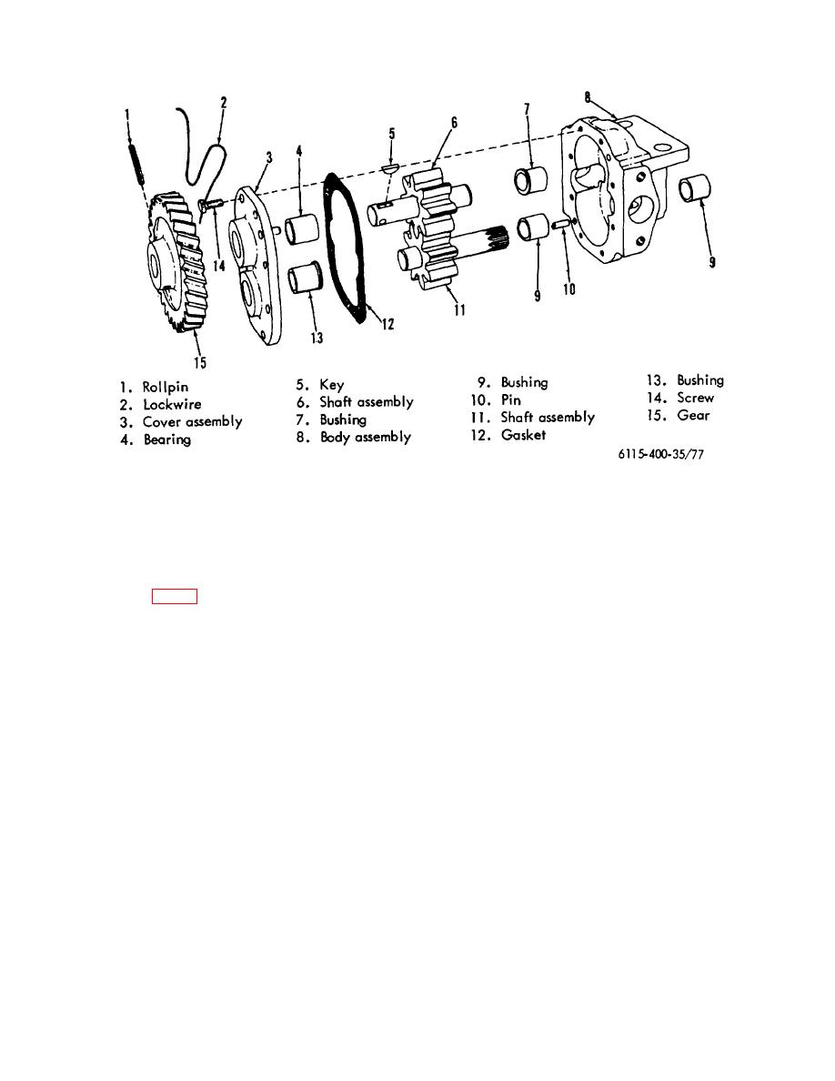
Figure 77. Oil pump-exploded view.
(c) Subtract the gear thickness from the
When the radial clearance exceeds .005
depth micrometer reading.
The
inch it will be necessary to replace worn
difference is the end clearance of
parts.
the gears.
(7) Remove upper shaft and gear assembly
(10) Inspect the pump cover bushings and
(6, fig. 77).
pump body bushings for wear or scoring
(8) Remove any burrs from splined end of the
and replace if necessary. The specified
lower shaft and remove shaft and gear
clearance between upper and lower shafts
assembly from the pump body.
and the bushings is .0015 inch-.003 inch.
(9) The maximum allowable end clearance of
After installing new bushings in the pump
the gears to the pump body is .007 inch.
body and in the pump cover, the bushings
The clearance may be checked as
should be reamed to .7495 inch-.7505
follows:
inch. The specified diameter of the upper
(a) Measure the thickness of the gears
and lower shafts at the bushing locations
with a micrometer. Make note of
is .7475 inch -.7480 inch.
the figure.
(11) Install the plain bushing in the upper shaft
(b) Place a new gasket on the cover
bore and the flanged bushing in the lower
face of the pump body. Place a
shaft bore in the pump cover. The two
depth micrometer in position on the
bushings must be flush with or below the
gasket, and pressing firmly measure
machined inner surface of the pump
the depth of the counterbore at a
cover.
point of gear contact.
111


