TM 5-6115-400-35
in the holes in the bearing cap. Attach the
pressure pump to the bearing cap with
capscrews and lockwashers and secure
with locking wire. The specified backlash
between the oil pump driving gear and the
crankshaft gear is .006 inch to .014 inch.
(2) Install the oil pump suction tube using a
new gasket between the suction tube and
the pump.
(3) Place the oil pump discharge tube and oil
pressure relief valve, as an assembly, in
position on the pump and the cylinder
block, using a new gasket at each end of
the discharge tube. Attach the discharge
tube to the cylinder block and pump with
capscrews and lockwashers. Secure the
capscrews with locking wire.
52. Piston Cooling Oil Jets
a. General.
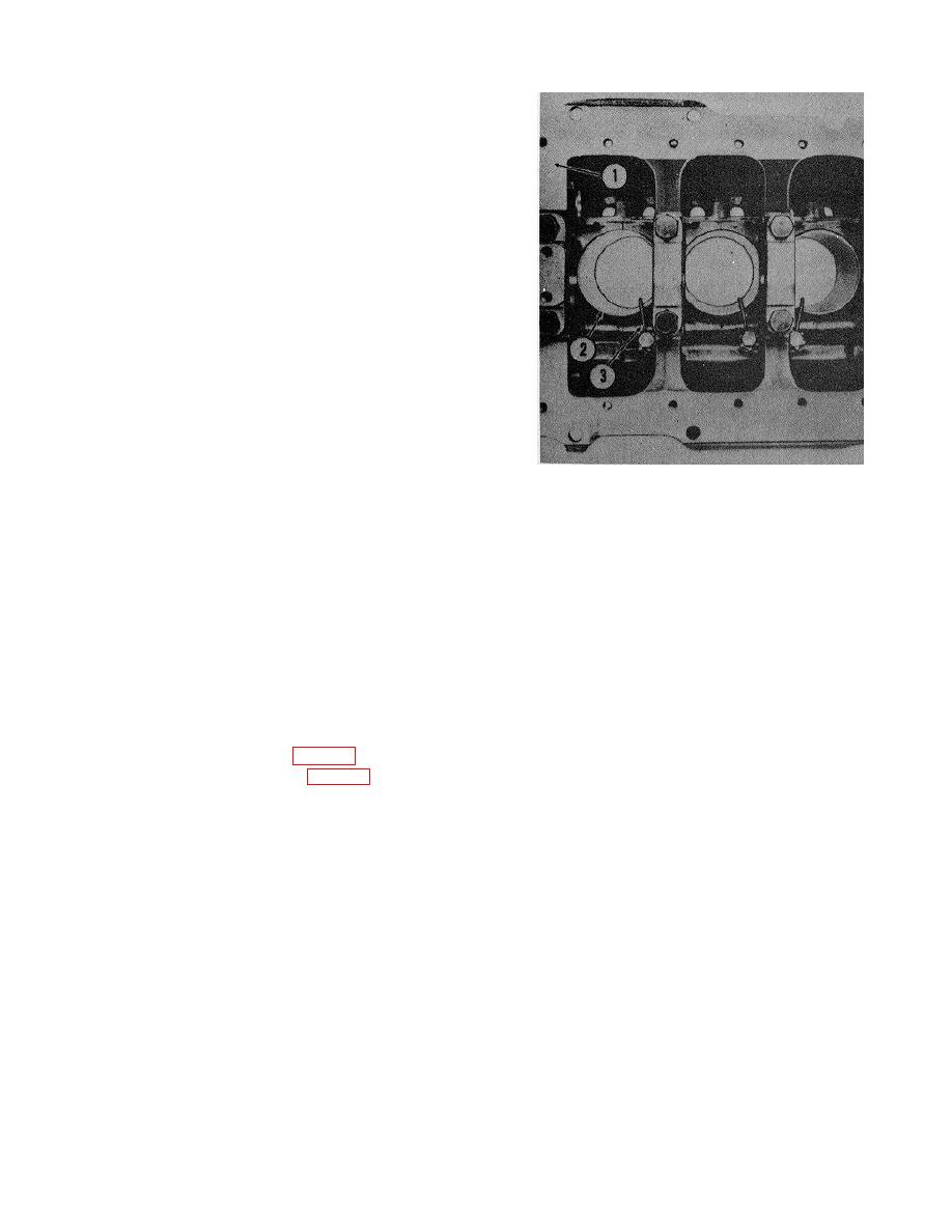
(1) Piston cooling oil jets are provided for
each cylinder; the jets are positioned with
1. Cylinder block
dowel pins in the crankcase along the
2. Cylinder sleeve
main oil gallery which supplies the oil to
3. Oil jet
the jets. Continuous oil spray, from the
6115-400-35/79
jets, cools the pistons during engine
operation.
Figure 79. Piston cooling oil jets.
(2) Whenever
the
engine
is
being
disassembled, the oil jets should be
(4) Thoroughly wash all parts in a cleaning
removed, inspected, and cleaned. The oil
solvent. If necessary, use a wire brush to
jets should be removed and ,installed
clean any sludge from oil jet nozzles,
while the crankshaft and pistons are in
being careful not to turn or bend nozzles.
place in the cylinder block so clearance
The size of the oil outlet hole in the nozzle
between the oil jets and these moving
is .109 inch-.1112 inch.
parts can be checked.
(5) If the silver solder between the jet union
b. Removal, Cleaning and Inspection.
and the nozzle is broken, resolder or
(1) Remove the oil pan (para 50).
preferably, replace the oil jet.
(2) Remove the oil pump (para 51).
Note. There are six oil jets, three
(3) Turn the crankshaft to obtain access to an
right hand (for cylinder Nos. 3, 5, and
oil jet. Remove the retaining capscrew
6) and three left hand (for cylinder Nos.
and lockwasher securing the oil jet to the
1, 2, 4). When ordering replacement
cylinder block and remove jet. Following
parts, be certain to specify if the oil jet
this procedure remove all jets noting at
is right or left hand.
which cylinder location each jet was
(6) Check the gage height of the dowel pins;
originally installed.
the specified dimension is 1/4 inch. The
diameter of the dowel pin is .1218 inch-
.1223 inch.
113


