TM 5-6115-400-35
(2) Install lower shaft and gear assembly in
the pump body, inserting splined end of
the shaft through the pump body
bushings.
(3) Install upper shaft and gear assembly in
the pump body, with end of the shaft
containing the keyway facing toward the
cover end.
(4) Install the pump cover and gasket in
position on the pump body and dowel
pins; secure with capscrews and locking
wires.
Note. It is recommended that a new
cover gasket he used.
(5) Install the key in the keyway of the upper
shaft. The interference fit between the
pump driving gear and the upper shaft is
.001 inch-.0025 inch. Heat the pump
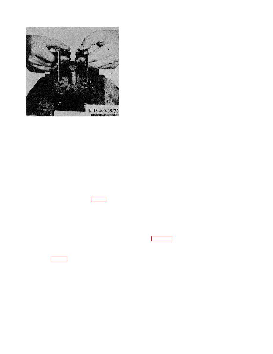
Figure 78. Checking radial clearance between
driving gear in lubricating oil to a
gear teeth and pump body.
temperature of approximately 260 .
F
Coat shaft, at gear location, with a
Three bushings are installed in the pump
mixture of white lead and oil; press gear
body bores; the flanged bushing in the
into position on the shaft.
upper shaft bore and the two plain
Note. When installing the driving
bushings in the lower shaft bore. The
gear onto the shaft, press gear onto
upper shaft bushing must be installed so
shaft only far enough to aline the holes
inner end (gear end) of the inner bushing
for the roll pin.
is 1/32 inch in from the inner machined
(6) The specified clearance between the
face of the body; the outer end of outer
driving gear and front machined face of
bushing should be located 1/32 inch in
the cover is .010 inch-.029 inch. Install
from outer face of the pump body.
the roll pin in position in the driving gear
(12) Remove, disassemble, and inspect the
and shaft. Secure by peening the gear
pressure relief valve (3, fig. 76).
hub over each end of the pin.
The piston must slide smoothly in the bore
e. Installation. All attaching capscrews, used on
of the valve body. When the piston or
the oil pump and associated tubing, are drilled head
bore of the valve body shows excessive
capscrews and MUST be locked with locking wire after
wear or roughness, a new valve assembly
they are installed and tightened to the proper torque.
must be installed.
This will prevent their working loose and causing
(13) Clean valve parts, reassemble, and
possible serious damage to the engine.
reinstall the valve in the pump discharge
See figure 76.
tube.
(1) Position the oil pump under the front main
(14) Remove and clean the oil screen and
bearing cap and turn the pump driving
reinstall in the oil screen cover.
gear until it meshes with the crankshaft
d. Assembly (fig. 77).
gear. This will allow the hollow dowels,
located in the pressure pump body, to
(1) Lubricate the bushings and shaft and gear
position
assemblies with clean engine oil.
112


