TM 5-6115-376-13
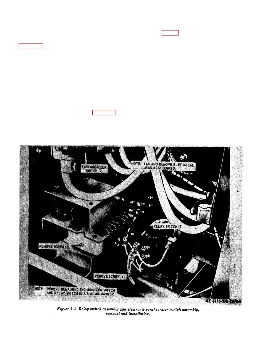
defective electronic synchronizer switch. Install
number one to operate until generator number two
electronic synchronizer switch in reverse order
is put on the line.
of removal (fig. 6-9). Install rear access panel.
g. Relay Switch Removal, Inspection and In-
stallation, Remove rear access panel, refer to
Switchbox (PU-699/M)
a. General. The switchbox is mounted on the
necessary; remove four mounting screws and re-
roadside fender of the PU-699/M. Its purpose is
move relay switch. Inspect all parts for damaged
to connect 3-phase power from one of two power
threads, cracks, breaks or other obvious defects.
sources (PU-699/M or PU-700/M, 60KW, gener-
Replace a defective relay switch. Install relay
ator sets) to a load. The power cable of the
switch in reverse order of removal; install rear
PU-699/M is connected to Gen 1 of the switchbox,
access panel.
and the power cable from the distribution box of
PU-699/M is connected to Load 1 of the switch-
h. Electronic Synchronizer Switch, The syn-
box. The power cable from the DE of the PU-700/
chronizer assembly contains two electronic syn-
M is connected to Gen 2 of the switchbox, and
chronizer switches of solid state design each
power cable from distribution box of PU-700/M
consisting of three plug-in type modules, t w o
is connected to Load 2 of the switchbox. Parallel-
transformers, transistors, diodes and capacitors.
ing of the two 60KW generator sets is automati-
Remove rear access panel. Refer to figure 6-9, tag
cally controlled. Control of power is by four
and disconnect electrical leads; remove two
circuit breaker switches.
mounting screws and remove electronic synchro-
b. Circuit Breaker Switches. The four circuit
nizer. Inspect all parts for cracks, breaks, loose
breaker switches on the switchbox should operate
connections, and other obvious defects. Replace a


