TM 9-6115-658-13&P
4-24
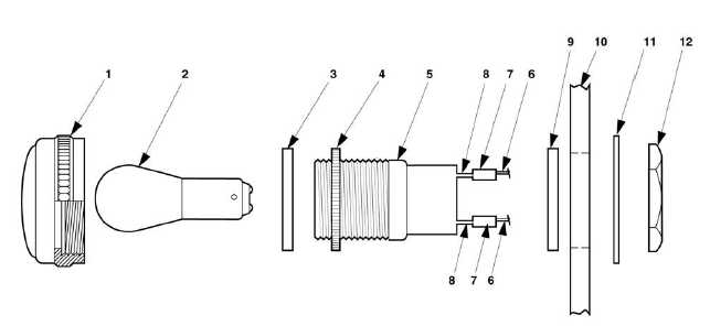
INSTALLATION
1. Insert terminal leads (7) through opening in switch box housing (10) and pull through until O-ring (9)
rests against switch box cover (10).
2. Install lock washer (11) and mounting nut (12).
3. Connect terminal lugs (8) to switch box components in accordance with Table 4-2.
4. Insert lamp (2) and O-ring (3) into lens (1).
5. Install lens (1) into housing (4) and hand tighten.
4-15 LIGHT SYNCHRONIZING MAINTENANCE.
This task covers:
a. Test
c. Installation
b. Removal
INITIAL SETUP
Tools
Equipment Conditions
Tool Kit, General Mechanic’s
Reference
(item 1, Appendix B)
Both generator sets shut down,
Materials/Parts
paragraph 2-5.3.3.
Switch box cover open.
Solder
Figure 4-12. Light/Lamp Synchronizing.