TM 9-6115-604-34
NAVFAC P-8-633-34
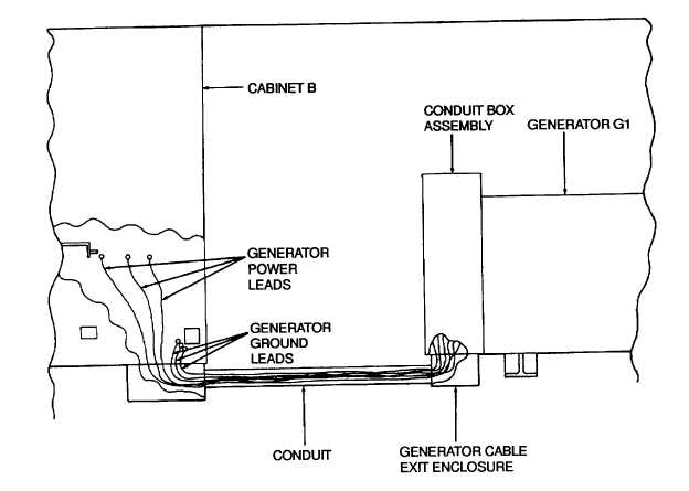
Figure 2-14. Generator, Ground and Power Leads Routing
(15)
Remove the cover and screen assembly (3, Figure 2-3) by removing nuts (1) and screws (2).
(16)
See Figure 2-4, detail B. Bend back the corners of the locking plates and remove the hexagon head
capscrews to disconnect the generator drive discs from the engine flywheel. Remove hexagon head
capscrews from the 3 and 9 o'clock positions first and install guide pins before removing remaining
hexagon head capscrews.
NOTE
Locking plates should be replaced and not reused.
(17)
See Figure 2-4. Remove the hexagon head capscrews, hexagonal nuts, and lockwashers from the
generator mounting feet.
WARNING
Use of chains and hoists not rated for the weight of the generator may result in Injury to
personnel or damage to equipment
(18)
See Figure 2-9. Connect the lifting rig to the lifting lugs on the generator housing and connect the lifting rig
to the hoist and take up slack from lifting device, but do not lift generator at this time.
(19)
See Figure 2-4, detail A. Remove the hexagon head capscrews and washers securing the adapter to the
flywheel housing. Start with the screws nearest the 12 o'clock position and work back and forth around the
circle down to the 6 o'clock position.
2-41