TM 9-6115-604-34
NAVFAC P-8-633-34
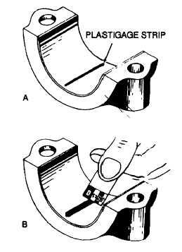
Figure 9-32. Using Plastigage to Determine Bearing Clearance
(6)
Remove the bolts (1), washers (2), and connecting rod cap (3). Compare the width of the compressed
Plastigage to the graduations on the Plastigage envelope (B. Figure 9-32). This is the connecting rod journal
clearance and must conform to the specifications in Table 1-4.
(7)
If the clearance is under the specifications given in Table 1-4, remove the bearings shells (11, Figure 9-24) and
check for oversize bearing shells, or the presence of foreign matter between the bearing shells and the
connecting rod (4) or cap (3).
(8)
If the clearance is over the specifications given in Table 1-4,install new bearing shells (11) and re-check the
clearance. If the clearance is still excessive, rebuild the crankshaft (32) in accordance with paragraph 9-28.
CAUTION
Before Installing the connecting rod bolts (1) and washers (2), coat the bolt threads, the
underside of the bolt heads, and the washers with clean lubricating oil MIL-L-2104. Failure to
do so will result In Improper torque and possible engine damage due to loosening of the
bolts.
(9)
If the clearance is satisfactory, remove all traces of Plastigage from the bearing shell and crankshaft journal,
lubricate the bearing shells and journal with a small amount of lubricating oil MIL-L-45199, and reinstall the
connecting rod cap (3), washers (2), and bolts (1). Tighten the bolts in accordance with Table 9-3.
(10)
Using a feeler gage, check the connecting rod side clearance. Connecting rod side clearance shall be 0.012 to
0.020 inch (0.30 to 0.51 mm), and the rods must be free to move sideways on the crankshaft (32). i the
connecting rods do not move freely on the crankshaft, or the clearance is not to specifications, check for
improper bearing shell installation or crankshaft thrust surface wear. Rebuild a worn crankshaft in accordance
with paragraph 9-28.
(11)
Repeat steps c through e, above, for each connecting rod bearing shell to be replaced.
9-60


