TM 9-6115-604-34
NAVFAC P-8-633-34
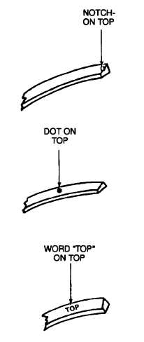
Figure 9-31. Identification of Top Side of Piston Ring
(b)
Identify the top of the piston rings in accordance with Figure 9-31.
CAUTION
Over-expanding a piston ring during removal or Installation will distort the ring and cause ring
failure. Do not expand the rings more than necessary during removal or Installation.
(c)
Making sure that the top of the piston ring faces the top of the piston, use piston ring expander ST-1 269,
and install the piston rings (5, 6, and 7, Figure 9-24) as follows:
1
Install the oil control ring (7) in the lower groove of the piston (10) with the gap located 90 degrees
from M the piston pin bore.
2
Install the intermediate compression ring (6) in the center groove of the piston (10) with the gap
located 180 degrees from the gap in the oil control ring (7).
3
Install the top compression ring (5) in the top groove of the piston (10) with the gap located 180
degrees from the gap in the intermediate compression ring.
9-56