TM 9-6115-604-34
NAVFAC P-8-633 34
(j)
Insert the mandrel ST-1 285-3 (1, Figure 9-28) through the bushing in the connecting rod (6).
(k)
Install the knock-out ring ST-1285-5 (2) and cup ST-1285-2 (3) on the mandrel (1) and secure the cup with
the pin ST-1 285-6 (4).
(I)
Insert the large end of the mandrel (1) in the hole of the block ST-1 285-1 (5).
(m)
Orient the taper of the knock-out ring (2) and the block (5) with the taper of the connecting rod pin (6), and
press out the piston pin bushing (13, Figure 9-24) using an arbor press. Disassemble ST-1 285, and
discard the bushing.
(n)
Place new bushing over the mandrel (1, Figure 9-28) and install the driver ST-1 285-4(7) and cup (3) on
the mandrel. Secure the cup with the pin (4).
(o)
Insert the mandrel (1) through the connecting rod piston pin bore (6) into the block (5).
(p)
Insert the mandrel ST-1 285-3 (1, Figure 9-28) through the bushing in the connecting rod (6).
(q)
Install the knock-out ring ST-1 285-5 (2) and cup ST-1 285-2 (3) on the mandrel (1) and secure the cup
with the pin ST-1 285-6(4).
(r)
Insert the large end of the mandrel (1) in the hole of the block ST-1 285-1 (5).
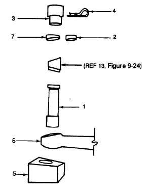
1. MANDREL (ST-1285-3)
2. KNOCK-OUT RING (ST-1285-5)
3. CUP (ST-1 285-2)
4. PIN (ST-1285-6)
5. BLOCK (ST-1 285-1)
6. CONNECTING ROD
7. DRIVER (ST-1 285-4)
Figure 9-28. Removal and Installation of Connecting Rod Piston Pin Bushing Using ST-1285
(s)
Orient the taper of the knock-out ring (2) and the block (5) with the taper of the connecting rod pin (6), and
press out the piston pin bushing (13, Figure 9-24) using an arbor press. Disassemble ST-1 285, and
discard the bushing.
(t)
Place new bushing over the mandrel (1, Figure 9-28) and install the driver ST-1285-4 (7) and cup (3) on
the mandrel. Secure the cup with the pin (4).
(u)
Insert the mandrel (1) through the connecting rod piston pin bore (6) into the block (5).
(v)
Orient the tapers of the block, connecting rod, bushing, and driver. Press the bushing into connecting rod
until the driver is flush with the connecting rod bore surface.
(w)
Disassemble ST-1 285, and check to see that the lubrication hole in the bushing is aligned with the
lubrication passage in the connecting rod.
9-52