TM 9-6115-604-34
NAVFAC P-8-633-34
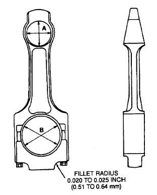
A-
PISTON PIN BUSHING BORE
NEW MINIMUM 2.4010 INCHES (60.985 mm)
NEW MAXIMUM 2.4015 INCHES (60.998 mm)
WORN LIMIT 2.4025 INCHES (61.023 mm)
B -
CONNECTING ROD BORE
MINIMUM 4.5017 INCHES (114.343 mm)
MAXIMUM 4.5027 INCHES (114.368 mm)
Figure 9-26. Connecting Rod Inspection
e. Inspect and Repair.
NOTE
During inspection, be sure the connecting rod (4, Figure 9-24) and its mating cap (3) are kept
together at all times. If either the connecting rod or cap is found to be defective, replace both
rod and cap.
(1)
Check the fillet radius where the cap is milled for the bolt head for damage (Figure 9-26). The fillet radius shall
be 0.020 to 0.025 inch (0.51 to 0.64 mm) and free of nicks and deep scratches, and the bolt head area must be
flat. A maximum of 0.0625 inch (1.588) may be milled from the cap to restore flatness and the radius.
(2)
Check the rod and cap for nicks, dents, and scratches. Replace both rod and cap if either has defects over 0.625
inch (1.588 mm) deep. Remove defects under 0.625 inch (1.588 mm) deep by grinding or filling. The ground or
filed area must have a radius of at least 0.5 inch (13 mm). Blend and polish the ground or filed area using
crocus cloth P-C-458.
(3)
Check the connecting rods (4, Figure 9-24), caps (3), and connecting rod bolts (1), for cracks using magnetic
particle inspection in accordance with MIL-L-6868. Pay particular attention to the critical areas around the crank
pin boss. piston pin boss and radius areas.
(4)
Assemble the cap to the rod with the dowels in place and cross tighten the bolts to operating tension in
accordance with Table 9-3.
9-49