ARMY TM 9-6115-604-12
NAVY NAVFAC P 8 633-12
b.
Remove. See Figure 4-65.
(1) Tag and disconnect wires from heater terminals.
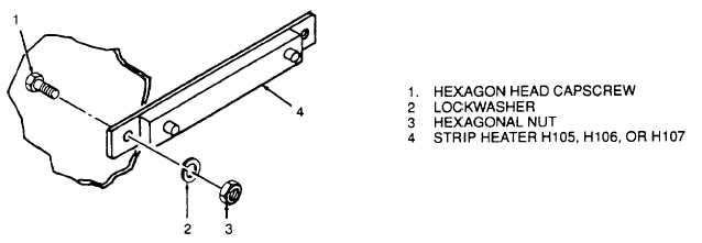
(2) Remove hexagon head capscrews (1), lockwashers (2), and hexagonal nuts (3) to remove strip heater H105,
H106, or H107 (4).
Figure 4-65. Removal and Installation of Strip Heaters
c.
Install. See Figure 4-65.
(1) Position heater (4).
(2) Secure heater using hexagon head capscrews (1), lockwashers (2), and hexagonal nuts (3). Connect wires
to terminals and discard tags.
4-97.
AC AMPERES METER M102 (1, Figure 2-2). AC AMPERES meter M102 indicates the amount of current
flowing through each individual phase of generator G1.
a.
Adjust. With generator set shut down, check that needle on AC AMPERES meter M102 Indicates at the zero
adjust point marked on the face of the meter If necessary, adjust the screw on the face of the meter to align the
needle with the mark.
b.
Remove. See 4-66.
(1) Open cabinet B door. Tag and disconnect wiring from AC AMPERES meter M102 (1).
(2) Remove screws and remove AC AMPERES meter M102 (1) from front of cabinet B door.
c.
Test.
(1) Connect AC AMPERES meter to a variable output current power supply. The meter movement requires one
milliamperer DC for full scale meter deflection.
(2) Turn on power supply.
(3) Increase output of power supply and note reading on AC AMPERES meter being tested. If value on meter
differentiates from known output of power supply by more than 2 percent of output value, replace meter.
(4) Turn off power supply.
(5) Disconnect meter.
4-163