ARMY TM 9-6115-604-12
NAVY NAVFAC P 8 633-12
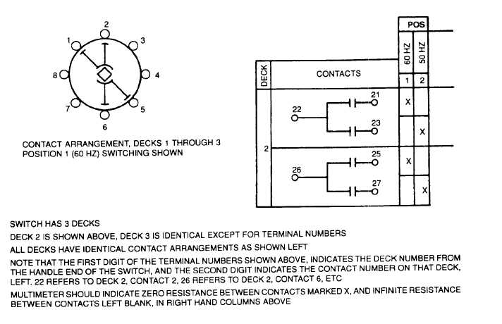
Figure 4-64. Test Data for FREQUENCY SEL SW S118
(2) Switch shaft should be rotated to the clockwise position (50 Hz) and the knob, when attached, should be
aligned with the 50 Hz marking.
(3) Install knob on shaft and tighten screw in center of switch.
(4) Connect wires and discard tags.
4-96.
SWITCHGEAR HEATERS H105, H106, AND H107. Strip heaters provide heat to switchgear cabinets to prevent
moisture from forming. See Figure 3-26, Figure 3-28, and Figure 3-29 for locations of strip heaters Remove switchgear
access panels in accordance with paragraph 4-18 and proceed as follows:
Burns may result, if heaters are not allowed to cool before attempting any
maintenance.
a.
Test.
(1) Tag and disconnect wires from heater terminals.
(2) Set multimeter to RX1 K scale and check heater for continuity (not open or shorted) and to ensure that
resistance is approximately 290 f 45 ohms.
(3) With multimeter, check for infinite resistance between heater terminals and case. Reading should be Infinity.
(4) Connect wires and discard tags.
4-162


