ARMY TM 9-6115-464-34
AIR FORCE TO 35C2-3-445-2
NAVY NAVFAC P-8-624-34
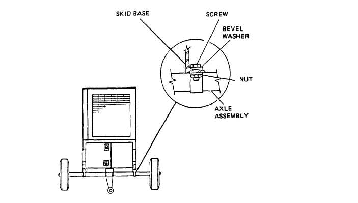
Figure 5-12. Wheel Mounting Kit Installation
5-18. AXLE ASSEMBLIES.
a. Removal. Refer to paragraph 5-15 for axle assembly removal instructions.
b. Disassembly.
(1)
(2)
(3)
(4)
(5)
(6)
(7)
(8)
(9)
NOTE
Disassemble wheel mounting kit only as necessary to replace defective parts.
Refer to the Operator and Unit Maintenance Manual and remove the wheels, tires brakes, and wheel
bearings.
Remove nut (1, figure 5-13), rod (2), bolt (3), Iockwasher (4), nut (5), spacer (6), cotter pin (7),
washer (8), pin (9), hand lever assembly (10), and yoke (11).
Remove cotter pin (12), yoke pin (13), and yoke (14).
Remove nut (15), Iockwasher (16), bolt (17), pin (18), level (19), grease fitting (20), and bearing
block (21).
Remove nut (22), rod (23), pin (24), and yoke (25).
Remove pin (26), yoke (27), pin (28), lever (29), and cross shaft (30).
Remove nut (31), Iockwasher (32), bolt (33), and lever (34).
Remove nut (35), Iockwasher (36), bolt (37), backing plate (38) and rear axle (39).
Remove cotter pin (40), nut (41), bolt (42).
5-31