TM5-6115-634-14&P
NAVFAC P-8-647-14&P
T0-35C2-3-445-14
TM-6115-14&P/1
4-17.
REPLACE CONNECTOR PLATE (cont)
b.
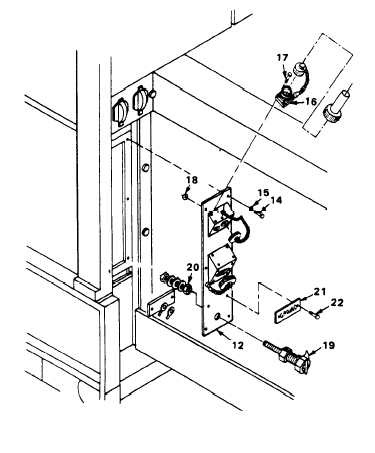
Install ground terminal (19)
with brass nut (20).
c.
Install connector ALT recep-
tacle (16) with four screws
(17), and nuts (18).
d.
Install connector plate (12)
with six screws (14), and lock-
washers (15).
2.
INSTALL PARALLEL/CONTROL CABLE
HEADS.
a.
Insert each cable head into
the connector plate (12).
b.
Install the locking nut (13)
onto each cable head and
tighten.
3.
REPLACE POWER CABLE HEAD.
a.
Insert the power cable head
(11) into the connector plate
(12).
b.
Install three surge suppressors
(4) with screws (5), lockwashers
(6), flat washers (7) and
(8).
c.
Secure the power cable by
stalling four screws (9),
(10) and captive washers.
4.
INSTALL GROUND CABLE.
Install ground cable with
washers (2) and brass nut
self-locking.
5.
CLOSE LEFT REAR ACCESS DOOR.
nuts
in-
nuts
two
(1),
NOTE
Connect
FOLLOW ON MAINTENANCE:
Negative Battery Cable (Para.
4-10).
4-23

