TM5-6115-634-14&P
NAVFAC P-8-647-14&P
T0-35C2-3-445-14
TM-6115-14&P/1
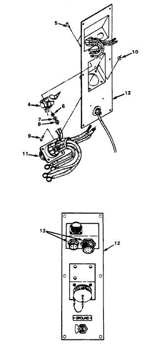
4-17. REPLACE CONNECTOR PLATE (cont)
3. REMOVE POWER CABLE HEAD.
a.
Remove surge suppressors (4),
by removing three screws (5),
lockwashers (6), flat washers
(7) and nuts (8).
b. Remove four screws (9) and nuts
(10).
c.
Backout power cable head (11)
from the connector plate (12).
4. REMOVE PARALLELING/CONTROL CABLE
HEADS.
a.
At the front of the connector
plate (12), remove the locking
nuts (13) from the two cable
heads.
b.
Remove each cable head from
the connector plate (12).
5.
REMOVE CONNECTOR PLATE.
a.
b.
c,
d.
Remove six screws (14) and
lockwashers (15) and remove
connector plate (12).
Remove connector ALT, recep-
tacle (16), by removing four
screws (17) and nuts (18)
w/captive washer.
Remove ground terminal (19)
by removing brass nut (20).
Remove nameplate GROUND (21)
by removing two screws (22).
INSTALLATION
1.
INSTALL PLATE CONNECTOR.
a.
Install nameplate GROUND with
two screws (22).
4-22