TM5-6115-634-14&P
NAVFAC P-8-647-14&P
T0-35C2-3-445-14
TM-6115-14&P/1
MAINTENANCE OF INTAKE BAFFLE ASSEMBLY
4-16.
REPLACE FLANGE, BOTTOM, LOWER AND UPPER SIDE
This task covers: a. Removal
b. Installation
INITIAL SETUP
Tools
General Mechanic’s
5180-00-177-7033
Materials/Parts
Flange Bottom
97403-13228E1950
Flange Lower Side
97403-13228E1943
Flange Upper Side
97403-13228E1921
Equipment Conditions:
Reference
Tool Kit
Para. 4-14 Baffle Assembly, Intake
Removed.
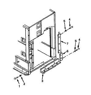
REMOVAL
1.
REMOVE FLANGE BOTTOM.
Remove four screws (1) and
lockwashers (2) and remove
bottom flange (3).
2.
REMOVE FLANGE LOWER SIDE.
Remove two screws (4) and
lockwashers (5) and remove
lower side flange (6).
3.
REMOVE FLANGE UPPER SIDE.
Remove three screws (4) and
and lockwashers (5) and remove
upper side flange (7).
INSTALLATION
1.
INSTALL FLANGE UPPER SIDE.
Install upper side flange (7)
with three screws (4) and
lockwashers (5).
4-19